


Wedge Wire Screen Dimensions
In industrial filtration and solids-liquid separation, the precision of equipment dimensions directly correlates with operational efficiency, maintenance frequency, and the longevity of the system. For engineers and procurement specialists, understanding the technical nuances of wedge wire screen dimensions is essential for specifying components that can withstand high-pressure environments while maintaining accurate particle retention.
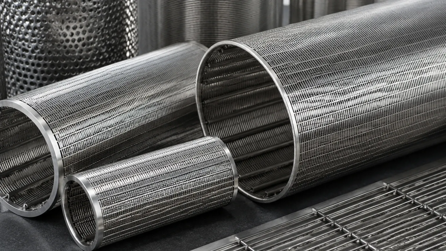
Wedge wire screens, characterized by their V-shaped profile wires and longitudinal support rods, offer a non-clogging surface that is superior to woven wire mesh in many heavy-duty applications. However, the performance of these screens is entirely dependent on the specific geometry of the wire, the accuracy of the slot opening, and the structural spacing of the support members.
Understanding the Fundamentals of Wedge Wire Geometry
The unique construction of Wedge Wire Screens involves resistance welding a continuous profile wire onto a series of support rods. This creates a screen that is structurally rigid and possesses a precise slot width.
When discussing wedge wire screen dimensions, we are typically referring to three distinct categories of measurement:
1. Functional Dimensions: The slot size (aperture) that determines filtration accuracy.
2. Component Dimensions: The width, height, and shape of the profile wires and support rods.
3. Physical Dimensions: The overall length, width, diameter, and thickness of the finished screen assembly.
Each of these dimensions must be calculated based on the specific flow rate, pressure drop requirements, and the physical characteristics of the media being processed. Inaccurate dimensioning can lead to premature blinding, structural failure under hydraulic load, or insufficient throughput.
Critical Parameters: Slot Size and Filtration Accuracy
The slot size is perhaps the most critical of all wedge wire screen dimensions. It is the clear distance between two adjacent profile wires. Unlike woven mesh, where the aperture can shift under tension, the welded nature of wedge wire ensures that the slot remains consistent even under significant mechanical stress.
Slot Width and Tolerance
Slot sizes typically range from as small as 20 microns (0.02 mm) to 10 mm or more, depending on the application. For high-precision industries like pharmaceutical or fine chemical processing, tolerances are exceptionally tight. A variation of even a few microns can allow oversized particles to pass through, potentially damaging downstream equipment or contaminating the final product.
The V-Shape Advantage
The "wedge" in wedge wire refers to the tapered profile of the wire. The narrowest part of the opening is at the surface, widening inward. This dimensional characteristic ensures that any particle small enough to enter the slot will pass through without getting wedged halfway, a phenomenon known as "pegging" or "blinding." This self-cleaning geometry is a direct result of the specific height-to-width ratio of the profile wire.
Profile Wire and Support Rod Dimensions
The selection of profile wire and support rod dimensions is a balancing act between hydraulic efficiency and mechanical strength.
Profile Wire Selection
Profile wires are identified by their width and height. Common industrial sizes include designations such as 12S (1.0mm wide), 18S (1.5mm wide), and 22S (2.2mm wide).
- Width: A narrower wire increases the total open area for a given slot size, allowing for higher flow rates. However, narrower wires have less surface area to resist abrasive wear.
- Height: The height of the wire contributes to the structural stiffness of the screen and determines the "wear life." In highly abrasive applications, such as mining or pulp and paper, taller profile wires are specified to provide a larger sacrificial wear zone.
Support Rod Configurations
Support rods provide the skeletal framework for the screen. Their dimensions (diameter or rectangular cross-section) and the pitch (the distance between them) determine the collapse and burst pressure of the screen. For cylindrical filters used in high-pressure hydraulic systems, support rod spacing must be calculated to prevent the profile wires from deforming under the force of the fluid.
Calculating Open Area and Flow Capacity
One of the primary reasons engineers specify wedge wire screen dimensions with such precision is to control the percentage of open area. The open area determines the velocity of the fluid as it passes through the screen, which in turn affects the pressure drop (delta P).
The Open Area Formula
The percentage of open area for a wedge wire screen can be calculated using the following formula:
Open Area % = [Slot Size / (Slot Size + Wire Width)] × 100
For example, if an engineer specifies a 0.5 mm slot with a 1.5 mm wide profile wire, the open area is 25%. If the application requires a higher flow rate but the slot size must remain 0.5 mm, the engineer might choose a narrower 1.0 mm wire, which increases the open area to 33.3%.
Impact on Total Cost of Ownership
While maximizing open area reduces energy costs by lowering pressure drop, it can reduce the mechanical lifespan of the screen if the wires are too thin for the operating environment. A comprehensive engineering review should consider the total cost of ownership, weighing the initial cost and energy efficiency against the frequency of replacement cycles.
Structural Integrity and Mechanical Dimensions
Beyond the filtration surface, the overall physical dimensions of the screen must be compatible with the housing or vessel in which it is installed.
Cylindrical Screen Dimensions
For cylindrical Wedge Wire Screens, three dimensions are paramount:
- Outside Diameter (OD) / Inside Diameter (ID): Precise diameters are required to ensure a proper seal within the filter housing. For "flow-out-to-in" applications, the OD is the critical dimension; for "flow-in-to-out," the ID is prioritized.
- Overall Length: This includes the active screening length plus any un-slotted ends or end fittings (flanges, threaded connectors, or rings).
- Roundness (Circularity): In automated cleaning systems where a scraper or backwash arm rotates inside the screen, the tolerance for roundness is extremely tight to prevent mechanical interference or bypassed solids.
Flat Panel and Sieve Bend Dimensions
For flat panels used in vibratory decks or sieve bends used in dewatering, dimensions include:
- Length and Width: Must match the support frame dimensions exactly to prevent bypass at the edges.
- Arc Length and Radius: Specific to sieve bends, these dimensions determine the centrifugal force applied to the slurry, which dictates the separation efficiency.
Engineering Considerations for Material Selection
Dimensions are not static; they are influenced by the material's thermal and chemical properties. Kaifil utilizes various grades of stainless steel, including 304, 316L, and Duplex steels, to manufacture these components.
When specifying wedge wire screen dimensions for high-temperature applications, engineers must account for thermal expansion. If a screen is fixed at both ends within a rigid housing, an increase in temperature can cause the screen to buckle if the dimensions do not allow for expansion. Similarly, in corrosive environments, a "corrosion allowance" may be added to the profile wire dimensions to ensure the screen maintains its structural integrity over its intended service life.
Common Risks in Dimension Specification
Errors in dimensioning often stem from a lack of communication between the end-user and the manufacturer. Common risks include:
- Undersizing the Support Rods: This leads to structural failure in high-pressure or high-viscosity applications.
- Ignoring Effective Screen Area: The total physical area of the screen is not the same as the effective screening area. End fittings, weld rings, and support rod contact points reduce the actual area available for flow.
- Inconsistent Slot Tolerances: Using a manufacturer without advanced welding controls can result in inconsistent slot widths, leading to unpredictable filtration performance.
Engineering Checklist for Custom Wedge Wire Specifications
Before finalizing an order for custom filtration components, technical teams should confirm the following dimensional data:
1. Target Particle Retention: What is the minimum and maximum particle size to be removed?
2. Required Flow Rate: What is the maximum volume of fluid per hour?
3. Maximum Differential Pressure: What is the highest pressure the screen will encounter before cleaning or replacement?
4. Direction of Flow: Is the fluid moving from the inside out or the outside in?
5. Mechanical Interface: Are the end fittings compatible with existing piping? (e.g., NPT threads, ANSI flanges, or custom machined rings).
6. Abrasive/Corrosive Factors: Does the profile wire height need to be increased to account for wear?
By focusing on these technical details, engineers can ensure that the wedge wire screen dimensions are optimized for both performance and durability. Whether for a new installation or a replacement component, precise dimensioning is the foundation of a reliable industrial filtration system.
