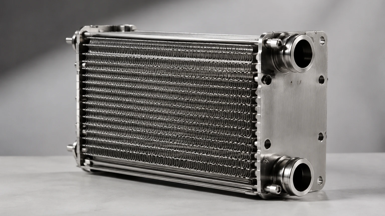
Fin and Plate Heat Exchanger
In industrial thermal management, the fin and plate heat exchanger (often referred to as a plate-fin heat exchanger or PFHE) represents one of the most efficient designs for achieving high heat transfer rates within a compact footprint. Characterized by its "sandwich" construction of corrugated fins and flat metal plates, this equipment is a staple in cryogenic air separation, aerospace environmental control systems, and complex chemical processing plants. For engineers and procurement specialists, understanding the technical nuances of these units—and the critical role of auxiliary components like precision filtration—is essential for ensuring long-term operational reliability.
Structural Design and Engineering Principles
The fundamental architecture of a fin and plate heat exchanger consists of a series of layers. Each layer includes a corrugated fin surface placed between two flat metal plates (parting sheets). These layers are sealed at the edges by side bars and stacked to form a core. The entire assembly is typically vacuum-brazed to ensure structural integrity and optimal thermal conductivity between the fins and the plates.
The Role of Fins
The fins serve two primary purposes: they significantly increase the secondary heat transfer surface area and provide structural support against internal pressure. Engineers select fin geometries based on the specific requirements of the fluid dynamics and thermal load:
* Plain Fins: Offer the lowest pressure drop but provide less turbulence, making them suitable for high-velocity gas streams.
* Serrated (Offset Strip) Fins: These involve cutting and shifting the fin segments to restart the boundary layer frequently. This maximizes heat transfer coefficients but results in a higher pressure drop.
* Wavy Fins: Provide a compromise between plain and serrated fins, inducing turbulence through a serpentine flow path without the sharp edges that might increase fouling risks.
* Perforated Fins: Feature small holes that allow for cross-flow between channels, helpful in specific multi-stream applications.
Plate and Bar Configuration
The parting sheets separate the different fluid streams, while the side bars contain the fluids within their respective layers. Because these exchangers can handle multiple streams (sometimes upwards of ten different fluids in a single block), the internal manifolding and header design are critical to ensure uniform flow distribution across all parallel channels.
The Relationship Between Heat Exchangers and Industrial Filtration
One of the most significant operational challenges for a fin and plate heat exchanger is its susceptibility to fouling and clogging. Because the flow channels created by the fins are often only a few millimeters wide, even microscopic particulate matter can accumulate, leading to increased pressure drop and reduced thermal efficiency.
This is where high-performance filtration becomes a prerequisite. To protect the intricate internal structures of the heat exchanger, engineers must implement robust filtration systems at the inlet. Kaifil specializes in manufacturing custom stainless steel filtration solutions designed to meet these exact requirements. By utilizing advanced wire mesh and sintered metal technologies, these filters ensure that the fluids entering the heat exchanger are free from contaminants that could compromise the narrow fin passages. For technical specifications on compatible filter cartridges and mesh components, professionals can visit the Main Page to review product options and application support.
Key Evaluation Criteria for Engineers
When specifying or evaluating a fin and plate heat exchanger for a B2B application, several technical parameters must be analyzed to ensure the unit meets the process requirements.
1. Surface Area Density
PFHEs are valued for their high surface area density, often exceeding 1,000 m²/m³. This allows for a much smaller installation footprint compared to traditional shell-and-tube exchangers. Engineers must confirm that the calculated surface area accounts for both primary (plates) and secondary (fins) surfaces, adjusted by the fin efficiency factor.
2. Thermal Effectiveness and NTU
The Number of Transfer Units (NTU) and the overall thermal effectiveness are vital for cryogenic applications where temperature approaches (the difference between the hot and cold stream temperatures) may be as low as 1-2 K. A high-performance fin and plate heat exchanger must be designed to handle these tight gradients without significant longitudinal heat conduction through the metal.
3. Pressure Drop Constraints
In many gas processing applications, the allowable pressure drop is extremely limited. The choice of fin density (measured in fins per inch or FPI) and fin type directly impacts the Fanning friction factor. Engineers must balance the desire for high heat transfer (which usually increases friction) with the power consumption of pumps or compressors.
4. Material Compatibility
While aluminum is the most common material for cryogenic PFHEs due to its excellent thermal conductivity and low-temperature ductility, stainless steel or nickel alloys are required for high-pressure or corrosive environments. Material selection must account for the brazing process, as the filler metal must be compatible with the base alloy to prevent galvanic corrosion or joint failure.
Common Operational Risks and Mitigation
Despite their efficiency, fin and plate heat exchangers are sensitive to specific failure modes that must be addressed during the design and maintenance phases.
* Particulate Fouling: As previously noted, the small hydraulic diameter of the channels makes them prone to blockage. If a heat exchanger becomes clogged, cleaning is exceptionally difficult due to the brazed, non-removable nature of the core. Preventive filtration is the only reliable strategy.
* Thermal Stress and Fatigue: Rapid temperature fluctuations (thermal cycling) can induce significant stress at the brazed joints between the fins and the parting sheets. This is particularly common in aerospace applications or batch processes. Design engineers must perform finite element analysis (FEA) to ensure the core can withstand the expected number of thermal cycles.
* Fluid Maldistribution: If the fluid is not distributed evenly across all parallel fin channels, "hot spots" or "cold spots" can occur. This reduces the overall effectiveness of the exchanger and can lead to localized thermal stresses. Proper header and nozzle design are essential to mitigate this risk.
Maintenance and Longevity
Because the core of a fin and plate heat exchanger is a monolithic brazed structure, it cannot be disassembled for mechanical cleaning. Maintenance strategies typically involve:
1. Chemical Cleaning: Using specialized solvents to dissolve scale or organic deposits. This requires careful selection of chemicals to ensure they do not attack the base metal or the brazing alloy.
2. Back-flushing: Reversing the flow to dislodge loose particulates, though this is often ineffective for deeply embedded debris.
3. Filtration Monitoring: The most effective maintenance is proactive. By monitoring the pressure differential across the inlet filters, operators can replace filter elements before contaminants reach the heat exchanger core.
High-quality stainless steel filter cartridges, such as those produced by Kaifil, provide the durability required for these demanding environments. These components are engineered to withstand high pressures and temperatures, ensuring that the protection system does not itself become a point of failure.
Technical Information for Procurement
Before initiating a purchase or custom design project for a fin and plate heat exchanger, the following data points should be confirmed and provided to the manufacturer:
* Fluid Properties: Density, viscosity, thermal conductivity, and specific heat capacity at operating temperatures for all streams.
* Flow Rates: Minimum, nominal, and maximum mass flow rates.
* Temperature Profile: Inlet and required outlet temperatures for each fluid.
* Pressure Limits: Maximum allowable working pressure (MAWP) and maximum allowable pressure drop ($ΔP$).
* Corrosion Allowance: Identification of any corrosive agents in the process stream that might necessitate specific alloys or coatings.
* Filtration Requirements: The required micron rating for inlet filters based on the fin spacing (typically, filtration should be at least 1/3 to 1/2 the size of the smallest flow passage).
Conclusion
The fin and plate heat exchanger remains a pinnacle of thermal engineering for applications requiring high efficiency and compact design. However, its performance is inextricably linked to the purity of the fluids it processes. By integrating precision-engineered filtration solutions with advanced heat exchanger designs, industrial facilities can achieve optimal thermal performance while minimizing the risk of costly downtime and equipment failure. For engineers seeking reliable filtration components to protect their thermal systems, exploring the resources available on the Main Page provides a foundation for selecting the right materials and specifications for any industrial environment.