


Disc Filter Diagram
In industrial filtration, the precision of a component’s design directly dictates the efficiency of the entire process. For engineers and procurement specialists, a disc filter diagram serves as more than just a visual aid; it is a technical blueprint that outlines the structural integrity, flow dynamics, and material composition of a filtration element. Understanding these diagrams is essential for selecting the correct Filter Discs & Packs for applications ranging from polymer melt filtration to hydraulic fluid purification.
This guide examines the technical nuances of disc filter diagrams, the engineering considerations behind their design, and how to interpret these specifications to ensure optimal performance in demanding industrial environments.
The Anatomy of an Industrial Disc Filter
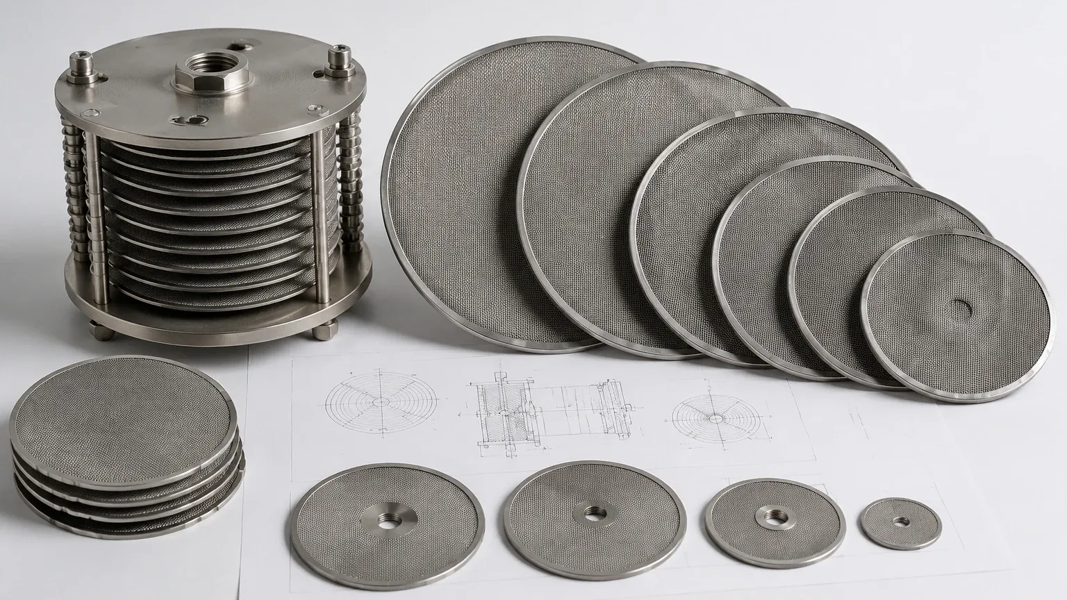
A comprehensive disc filter diagram typically illustrates the multi-layered construction required to balance filtration fineness with mechanical strength. Unlike simple mesh cutouts, industrial-grade filter discs often involve complex assemblies designed to withstand high differential pressures and corrosive environments.
1. The Filtration Layer
At the core of the diagram is the primary filtration media. This is usually a stainless steel wire mesh, which can be woven in various patterns such as plain weave, twill weave, or Dutch weave. The diagram specifies the wire diameter and the aperture size (micron rating). For high-precision applications, this layer is responsible for capturing particles of a specific size while maintaining a consistent flow rate.
2. Support and Drainage Layers
Single-layer discs are often insufficient for high-pressure systems. A detailed diagram will show a stack of layers where the fine filtration mesh is sandwiched between coarser support meshes. These layers prevent the fine mesh from deforming under pressure and provide a drainage path for the filtrate, ensuring that the entire surface area of the disc is utilized effectively.
3. The Rim or Binding
The outer edge of the disc is a critical focal point in any technical drawing. The rim provides structural rigidity and ensures a leak-proof seal within the filter housing. Diagrams will specify whether the disc is "naked" (mesh only), spot-welded at the edges, or bound with a metal rim made of aluminum, stainless steel, or copper. The width and thickness of this rim are vital for calculating the Effective Filtration Area (EFA).
Interpreting the Disc Filter Diagram for Performance
When reviewing a disc filter diagram, engineers must look beyond the basic dimensions to understand how the component will behave under operational stress. Several key performance indicators are embedded within the technical specifications of the drawing.
Effective Filtration Area (EFA)
The EFA is the total surface area of the mesh that is actually available for fluid passage. In a diagram, this is calculated by subtracting the area covered by the rim or support ribs from the total surface area. A common mistake in procurement is overlooking the EFA, leading to higher-than-expected initial pressure drops because the binding or support structure occupies too much of the mesh surface.
Layer Orientation and Sintering
In multi-layer or sintered filter discs, the diagram should indicate the orientation of the mesh layers. Sintered discs involve bonding multiple layers of mesh through a diffusion-bonding process (heat and pressure) without the use of binders. The diagram for a sintered disc will show a monolithic structure where the layers are inseparable, providing superior mechanical strength and preventing wire migration—a critical requirement in the pharmaceutical and food industries.
Flow Directionality
While many filter discs are symmetrical, some multi-layered packs are designed for specific flow directions. A technical diagram will often include an arrow or a cross-sectional view indicating which side should face the influent. This is particularly important in asymmetric sintered structures where a coarse layer acts as a pre-filter for a finer internal layer.
Engineering Considerations: Material and Weave Selection
The choice of materials and weave types, as specified in the disc filter diagram, is dictated by the chemical compatibility and the nature of the contaminants being filtered.
* Stainless Steel 304 vs. 316L: Most diagrams specify SS 304 for general industrial use, while SS 316L is reserved for environments involving high acidity, chlorides, or high temperatures, such as in chemical processing or marine applications.
* Dutch Weave Variations: If the diagram specifies a "Plain Dutch Weave" or "Reverse Dutch Weave," it indicates a design optimized for high pressure and fine filtration. Dutch weaves have more wires in one direction than the other, creating a tortuous path that enhances particle retention compared to simple square meshes.
* Specialty Alloys: For extreme conditions, diagrams may specify Hastelloy, Monel, or Inconel, which offer exceptional resistance to oxidation and thermal cycling.
Common Risks in Disc Filter Specification
Misinterpreting or underspecifying details in a disc filter diagram can lead to significant operational failures. Understanding these risks helps in making informed purchasing decisions.
1. Mesh Migration
In lower-quality discs, individual wires can break loose and enter the downstream flow. This is a major risk in food and beverage or pharmaceutical production. A well-engineered diagram will specify edge-binding techniques or sintering processes that mitigate this risk by securing all wire ends.
2. Pressure Drop and Collapse
If the support layers shown in the diagram are too thin or have an inappropriate mesh count, the disc may bow or collapse under high differential pressure. This not only bypasses the filtration process but can also damage downstream equipment like pumps or precision valves. Engineers should confirm that the support structure is rated for the maximum expected system pressure.
3. Bypass Leakage
If the tolerances for the outer diameter (OD) or the rim thickness are too loose in the diagram, the disc may not fit snugly within the filter housing. Even a microscopic gap can allow unfiltered fluid to bypass the media, compromising the purity of the final product.
Customization and OEM Requirements
Industrial applications often require customized Filter Discs & Packs that deviate from standard catalog sizes. When requesting a custom disc filter diagram from a manufacturer like Kaifil, several parameters must be confirmed:
* Shape and Geometry: While circular discs are standard, diagrams can be produced for oval, rectangular, or ring-shaped (annular) filters.
* Spot Welding Patterns: For multi-layer packs, the number and placement of spot welds are crucial. Too few welds lead to layer separation; too many can reduce the EFA or create stress points.
* Micron Rating Accuracy: The diagram should specify whether the micron rating is "absolute" (capturing 99% or more of particles at that size) or "nominal" (an average retention rate).
* Surface Treatment: Some applications require ultrasonic cleaning, passivating, or electro-polishing, which should be noted in the technical specifications to ensure the disc meets cleanliness standards.
Maintenance and Replacement Indicators
A technical disc filter diagram also assists maintenance teams in identifying when a component has reached the end of its service life. By understanding the original thickness and weight of the disc, technicians can measure the impact of repeated cleaning cycles.
In many high-viscosity applications, such as plastic extrusion, filter discs are cleaned and reused. However, each cleaning cycle (whether via burnout, chemicals, or ultrasonics) slightly degrades the wire diameter. Comparing a used disc against its original diagram specifications allows for a factual assessment of whether the mesh has thinned to the point of risking failure.
Conclusion: The Role of Technical Accuracy
In the B2B procurement process, the disc filter diagram is the primary tool for ensuring that the supplied components meet the engineering requirements of the system. It bridges the gap between the theoretical filtration needs of a process and the physical reality of the manufactured part. By focusing on material integrity, layer configuration, and precise rim dimensions, engineers can ensure they receive filtration solutions that offer longevity, reliability, and cost-effectiveness.
For those managing complex industrial systems, partnering with a manufacturer that provides detailed technical documentation and customization options is essential. A clear, accurate diagram is the first step toward achieving the precise filtration performance required in modern industrial environments.
