


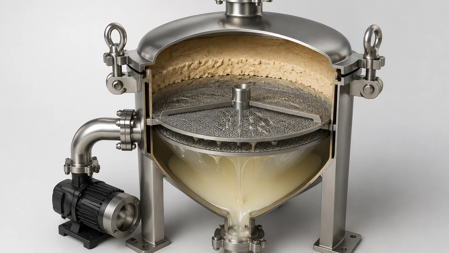
Vacuum Filter Diagram
In industrial liquid-solid separation, the vacuum filter serves as a cornerstone for continuous and batch processing. Understanding a vacuum filter diagram is essential for engineers and procurement teams tasked with optimizing filtration efficiency, ensuring material compatibility, and maintaining system integrity. A well-constructed diagram provides more than a visual representation; it outlines the pressure differentials, flow paths, and mechanical interfaces that define the performance of the filtration system.
For industries ranging from chemical processing to food and beverage production, the choice of filtration media—specifically stainless steel wire mesh and custom cartridges—is a critical variable in the system design. This guide examines the technical components of vacuum filtration systems, the engineering logic behind their diagrams, and the selection criteria for high-performance components.
Fundamentals of Vacuum Filtration Systems
Vacuum filtration operates on the principle of pressure differential. Unlike pressure filters that push slurry through a medium, vacuum filters create a low-pressure zone on the downstream side of the filter medium, using atmospheric pressure or a vacuum pump to pull the liquid (filtrate) through while retaining solids (filter cake) on the surface.
A standard vacuum filter diagram typically illustrates four primary zones: the feed zone, the cake formation zone, the washing/drying zone, and the discharge zone. In a B2B context, the precision of these zones determines the throughput and the purity of the final product. Engineers must account for the resistance offered by both the filter medium and the accumulating cake, a relationship often defined by the Darcy-Weisbach equation in hydraulic modeling.
Core Components in a Vacuum Filter Diagram
1. The Filter Medium: This is the heart of the system. In demanding industrial environments, stainless steel wire mesh or sintered metal cartridges are preferred for their mechanical strength and thermal resistance. The diagram must specify the micron rating and the weave type (such as plain, twill, or Dutch weave) to ensure the medium can withstand the vacuum pressure without deforming.
2. Vacuum Source: Usually a liquid ring vacuum pump or a dry screw pump. The diagram indicates the connection points and the required vacuum level, typically measured in inches of mercury (inHg) or millibars (mbar).
3. Filtrate Receiver: A vessel designed to separate the liquid filtrate from the air pulled through by the vacuum. This component must be sized to prevent carryover into the vacuum pump.
4. Support Structure: Because vacuum filtration exerts significant force on the filter medium, a robust support plate—often made of perforated stainless steel—is necessary to prevent the mesh from sagging or tearing.
Engineering Considerations for Stainless Steel Media
When reviewing a vacuum filter diagram for custom industrial applications, the material of the filter element is a primary technical boundary. Kaifil specializes in manufacturing stainless steel filtration solutions that address the specific stresses found in vacuum-driven systems.
Material Selection: 304 vs. 316L Stainless Steel
The choice between Grade 304 and Grade 316L stainless steel is dictated by the chemical composition of the filtrate. Grade 304 is suitable for general industrial use, providing excellent strength and basic corrosion resistance. However, in chemical processing or marine environments where chlorides are present, Grade 316L is required due to the addition of molybdenum, which enhances resistance to pitting and crevice corrosion. For engineers, the diagram should clearly label the metallurgy of all wetted parts to ensure long-term durability and prevent premature failure.
Mechanical Integrity Under Vacuum
Unlike positive pressure systems where the housing bears much of the load, in a vacuum filter, the filter medium itself is subjected to atmospheric pressure pushing against the vacuum. This creates a risk of "media migration" or structural collapse if the filter is not properly engineered. High-performance vacuum filter diagrams often include a multi-layer mesh design. This involves a fine filtration layer bonded to a coarser drainage layer and a heavy-duty support layer, providing a balance between high flow rates and structural rigidity.
Interpreting the Vacuum Filter Diagram for Process Optimization
For technical professionals, a vacuum filter diagram is a tool for troubleshooting and optimization. By analyzing the flow paths and instrument placement, engineers can identify potential bottlenecks or areas of energy loss.
Pressure Drop Monitoring
The diagram should feature pressure gauges or transmitters both upstream and downstream of the filter element. A rising differential pressure (ΔP) indicates cake buildup or media blinding. In automated systems, these data points trigger cleaning cycles or backwashing sequences. For stainless steel filters, understanding the maximum allowable ΔP is crucial; exceeding this limit can cause the wire mesh to stretch, altering the effective micron rating and compromising filtration accuracy.
Flow Rate and Viscosity
The efficiency of a vacuum filter is inversely proportional to the viscosity of the liquid. In the food and beverage industry, for example, syrups or oils require larger filtration areas or higher vacuum levels to maintain throughput. The vacuum filter diagram helps in calculating the "filter flux" (volume per unit area per unit time), allowing purchasing teams to size the equipment correctly based on their production targets.
Applications in Demanding Industrial Sectors
Industrial filtration requirements vary significantly across sectors. The versatility of stainless steel components allows them to be integrated into various vacuum filter configurations represented in technical diagrams.
Chemical and Pharmaceutical Processing
In these sectors, purity and containment are paramount. Vacuum filters are often used for catalyst recovery or the separation of active pharmaceutical ingredients (APIs). The vacuum filter diagram for these applications often includes "Clean-in-Place" (CIP) systems. Stainless steel is the material of choice here because it can withstand aggressive cleaning agents and high-temperature sterilization without degrading.
Food and Beverage Industry
Hygiene is the critical factor in food-grade vacuum filtration. Diagrams for these systems emphasize smooth internal surfaces and the absence of dead zones where bacteria could proliferate. Stainless steel wire mesh filters provide a non-leaching, easy-to-clean surface that meets stringent regulatory standards. Whether filtering juices, wines, or edible oils, the durability of metal filters reduces the risk of media fragments contaminating the product stream.
Hydraulic and Industrial Equipment
Vacuum dehydration is a common method for removing water and gases from hydraulic oils. The diagram for a vacuum dehydrator shows the oil being spread over a large surface area (often using specialized filter elements) under a vacuum to lower the boiling point of water. This process requires precision-engineered metal components that can handle high-viscosity fluids while maintaining fine particle retention.
Customization and OEM Capabilities
Every industrial process has unique requirements that a standard off-the-shelf filter may not meet. This is where customization becomes essential. When an engineer provides a vacuum filter diagram to a manufacturer like Kaifil, it serves as the basis for developing a bespoke solution.
Tailoring Pore Size and Geometry
Customization options include varying the pore size from sub-micron levels to several millimeters. The geometry of the filter—whether it is a flat disc, a pleated cartridge, or a cylindrical basket—must align with the housing dimensions shown in the system diagram. Pleated stainless steel cartridges are particularly effective in vacuum systems because they offer a significantly larger surface area within a compact footprint, reducing the frequency of cleaning cycles.
Integration with Existing Systems
For OEM projects, the filter component must integrate seamlessly with the existing vacuum infrastructure. This includes matching flange types, thread specifications, and sealing mechanisms (such as O-rings or gaskets made of Viton, EPDM, or PTFE). A detailed diagram ensures that the replacement or custom-built filter fits perfectly, preventing vacuum leaks that would otherwise undermine system efficiency.
Maintenance and Total Cost of Ownership
While the initial cost of stainless steel filtration media may be higher than disposable alternatives, the total cost of ownership (TCO) is often lower in industrial vacuum applications. A vacuum filter diagram that incorporates permanent, cleanable metal filters reduces waste and eliminates the recurring expense of replacement cartridges.
Cleaning Protocols
Stainless steel filters can be cleaned using several methods, including ultrasonic cleaning, backpulsing, or chemical baths. The diagram should account for the plumbing necessary to facilitate these cleaning processes without requiring the complete disassembly of the filter housing. Regular maintenance, guided by the technical specifications of the filter media, ensures that the vacuum system operates at peak efficiency for years.
Evaluating Performance Expectations
Before finalizing a purchase or a system design, engineers should confirm the following data points against their vacuum filter diagram:
* Maximum Operating Temperature: Ensuring the mesh and seals can handle the process heat.
* Chemical Compatibility: Verifying that the stainless steel grade is resistant to the process fluid.
* Filtration Accuracy: Confirming that the micron rating provides the required clarity without excessive pressure drop.
* Mechanical Load: Validating that the support structure can handle the maximum vacuum pressure.
For more information on selecting the right stainless steel filtration components for your specific industrial application, you can Review product options and application support on our Main Page.
Conclusion
A vacuum filter diagram is an indispensable technical document that bridges the gap between theoretical process design and practical industrial application. By focusing on the mechanical properties of stainless steel media and the hydraulic requirements of the vacuum system, engineers can design filtration solutions that are both durable and efficient. Whether you are troubleshooting an existing system or designing a new OEM project, understanding the nuances of the vacuum filter diagram ensures that you select the right components to meet your performance and purity goals.
