


Filter Coalescer Design
In industrial processing, the separation of immiscible liquids or the removal of liquid aerosols from gas streams is a critical requirement for protecting downstream equipment, ensuring product purity, and meeting environmental regulations. Filter coalescer design represents a sophisticated engineering discipline that combines mechanical filtration with the physical principles of phase separation. Unlike standard particulate filters that simply trap solids, a coalescer must facilitate the merging of sub-micron droplets into larger masses that can be easily drained by gravity.
For engineers and technical procurement teams, understanding the nuances of filter coalescer design is essential for optimizing system performance and reducing the total cost of ownership. This guide examines the technical foundations, material considerations, and engineering parameters necessary for effective liquid-liquid and gas-liquid separation.
Fundamentals of Coalescence Technology
Coalescence is a multi-stage process. To design an effective system, one must first understand how small droplets behave within a flowing medium. In most industrial applications, the goal is to separate a "dispersed phase" (the contaminant droplets) from a "continuous phase" (the main fluid stream).
The Three Stages of Coalescence
1. Capture: As the fluid passes through the coalescing media, the fine droplets come into contact with the fibers or mesh. This occurs through mechanisms such as inertial impaction, direct interception, and Brownian diffusion.
2. Coalescence: Once captured, the droplets attach to the media surface. As more droplets are intercepted, they migrate along the fibers and collide with one another, merging into larger droplets. This process is heavily influenced by the surface energy of the media.
3. Release and Separation: When the droplets reach a sufficient size, the drag force of the fluid stream or the force of gravity overcomes the adhesive forces holding them to the media. The enlarged droplets then detach and settle into a collection sump or rise to the top of the housing, depending on the density difference between the two phases.
Effective filter coalescer design relies on selecting media that provides a high surface area for capture while maintaining a structure that allows for the efficient drainage of the separated phase. For comprehensive technical specifications on the components used in these systems, engineers often refer to the Main Page of specialized manufacturers to evaluate material compatibility and mesh configurations.
Key Engineering Parameters in Filter Coalescer Design
Designing a coalescer is not a one-size-fits-all process. Several physical and chemical variables must be calculated to ensure the system operates within its intended efficiency range.
Interfacial Tension (IFT)
Interfacial tension is perhaps the most critical factor in liquid-liquid separation. It measures the cohesive force at the interface between two immiscible liquids. A high IFT (above 20 dynes/cm) usually indicates that droplets will coalesce easily. However, in the presence of surfactants or chemicals that lower IFT, droplets become stable and much harder to separate. In such cases, the filter coalescer design must incorporate specialized high-surface-energy media to break the emulsion.
Fluid Velocity and Flux Rate
The velocity of the fluid through the media directly impacts the residence time. If the velocity is too high, the drag forces may strip droplets from the media before they have grown large enough to settle, a phenomenon known as "re-entrainment." Conversely, if the velocity is too low, the system may become unnecessarily large and expensive. Engineers must calculate the optimal flux rate (flow per unit area) to balance separation efficiency with housing size.
Viscosity and Density Differential
According to Stokes' Law, the settling velocity of a droplet is proportional to the square of its diameter and the difference in density between the two phases, and inversely proportional to the viscosity of the continuous phase. Therefore, as the viscosity of the main fluid increases, the filter coalescer design must account for slower settling times, often requiring larger vessel diameters or specialized internal baffles.
Material Selection for Industrial Coalescers
The choice of material determines the durability and chemical resistance of the filter. In demanding industrial environments, such as chemical processing or oil and gas, stainless steel is the preferred material due to its structural integrity and resistance to corrosion.
Stainless Steel Wire Mesh
Stainless steel wire mesh is a cornerstone of robust filter coalescer design. By layering different mesh counts, engineers can create a gradient pore structure. The outer layers may act as pre-filters to remove solid particulates, while the inner layers provide the fine interstices required for droplet capture. Sintered wire mesh is particularly valued for its fixed pore geometry, which prevents media migration under high-pressure differentials.
Surface Chemistry and Coatings
In some applications, the media must be either hydrophobic (water-repelling) or hydrophilic (water-attracting) to enhance separation. For example, in a fuel-water separator, a hydrophobic coating on the secondary separator element ensures that only the fuel passes through while the coalesced water droplets are blocked and forced to settle.
Structural Components and Housing Design
A coalescer element is only as effective as the housing that contains it. The internal architecture of the vessel must manage flow distribution to prevent turbulence, which can break apart coalesced droplets.
Flow Direction
In gas-liquid coalescers, the flow is typically from the inside of the element to the outside. This allows the coalesced liquid to form on the outer surface of the media and drain down to the sump without being re-entrained by the high-velocity gas stream entering the center of the element. In liquid-liquid applications, the flow direction depends on the specific gravity of the phases and the orientation of the vessel (horizontal vs. vertical).
Pre-filtration Requirements
One of the most common causes of coalescer failure is solid particulate contamination. If solids clog the fine pores of the coalescing media, the pressure drop increases, and the coalescence process is disrupted. A sound filter coalescer design always considers the need for integrated or upstream pre-filtration to protect the delicate coalescing stages.
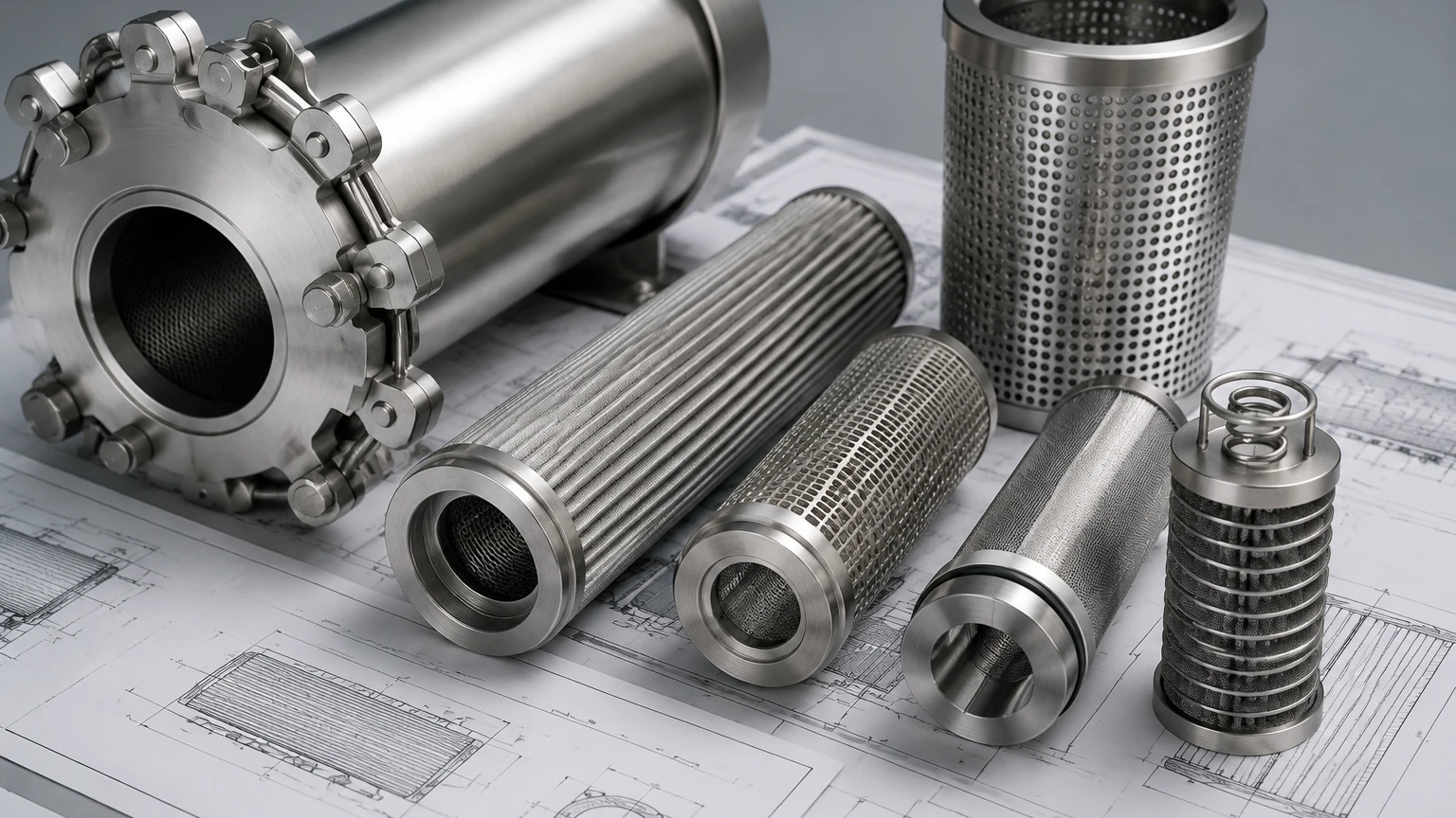
Performance Evaluation and Testing Standards
To validate a filter coalescer design, manufacturers and engineers use standardized testing protocols. These tests measure the efficiency of the filter in removing specific droplet sizes under controlled flow conditions.
* Pressure Drop (ΔP): The resistance to flow across the media. Engineers must monitor both the "clean" pressure drop and the "saturated" pressure drop, as the presence of captured liquid within the media increases resistance.
* Efficiency (Beta Ratio): For coalescers, efficiency is often expressed as the concentration of the dispersed phase in the effluent (e.g., < 5 ppm of water in diesel).
* Saturation Levels: This refers to the volume of liquid held within the media during steady-state operation. A well-designed coalescer reaches an equilibrium where the rate of capture equals the rate of drainage.
Customization and OEM Solutions for Demanding Applications
Standard off-the-shelf coalescers often fail to meet the specific requirements of complex industrial processes. Customization is frequently necessary to address unique chemical compatibilities, extreme temperatures, or space constraints.
When engaging in custom filter coalescer design, engineers should confirm the following with their manufacturing partner:
* Material Certification: Ensure the stainless steel grades (e.g., 304, 316L, 904L) meet the chemical resistance needs of the process.
* Micron Rating Accuracy: The pore size must be precisely calibrated to the expected droplet size distribution of the emulsion.
* Mechanical Strength: The element must withstand the maximum system pressure and potential pressure surges without collapsing.
Manufacturers like Kaifil specialize in providing these customized metal filtration components, offering the engineering expertise required to translate process data into functional hardware. By focusing on precision manufacturing and high-quality materials, these solutions ensure long-term reliability in sectors ranging from pharmaceutical production to hydraulic system maintenance.
Conclusion
Filter coalescer design is a vital component of modern industrial fluid management. By carefully considering the physics of droplet interaction, the rheology of the fluids involved, and the structural advantages of materials like stainless steel wire mesh, engineers can develop separation systems that are both highly efficient and durable.
As industrial requirements become more stringent regarding purity and environmental impact, the role of specialized coalescing technology will only grow. For those looking to implement or upgrade their filtration systems, focusing on the technical fundamentals and seeking out experienced OEM partners is the most effective path to achieving optimized performance. For further exploration of filtration components and custom manufacturing capabilities, visiting the Main Page provides a starting point for technical evaluation and product selection.
