


How Is Perforated Metal Made
Perforated metal is a fundamental component in industrial engineering, serving critical roles in filtration, acoustic dampening, structural support, and fluid dynamics. For engineers and procurement specialists, understanding how is perforated metal made is essential for specifying the correct materials, hole patterns, and tolerances for demanding applications. In the context of industrial filtration, perforated metal often serves as the structural backbone or the primary screening element, requiring high precision and structural integrity.
The manufacturing process involves more than simply punching holes in a sheet. It requires a sophisticated integration of mechanical engineering, material science, and precision tooling to ensure the final product meets the rigorous standards of sectors like chemical processing, pharmaceuticals, and hydraulic systems.
The Fundamentals of Metal Perforation
At its core, the perforation process involves the mechanical removal of material from a metal sheet or coil to create a pattern of holes. This is achieved through a shearing process where a punch and die set work in tandem. The punch descends into the material, and the die, located beneath the sheet, provides the necessary resistance to shear the metal cleanly.
The quality of the perforation depends heavily on the clearance between the punch and the die. If the clearance is too large, the metal will deform or leave significant burrs; if it is too small, the tooling will wear prematurely. In industrial filtration, where Perforated & Expanded Metal is used to support fine mesh or act as a coarse filter, the precision of these holes determines the flow rate and the pressure drop across the system.
Step-by-Step: How Is Perforated Metal Made?
The production cycle for perforated metal follows a structured sequence designed to maintain material flatness and pattern accuracy.
1. Material Selection and Preparation
The process begins with selecting the appropriate alloy. In the filtration industry, stainless steel (typically grades 304, 316, or 316L) is the standard due to its corrosion resistance and mechanical strength. The material is supplied either in large coils or individual sheets. Coils are preferred for high-volume, continuous runs, while sheets are used for custom or heavy-gauge applications.
2. Tooling Configuration
Engineers determine the tool layout based on the required pattern—staggered or straight. A "die set" is installed into the press, containing the punches that will create the holes. For filtration components, the hole size and pitch (the distance between the centers of the holes) are calculated to achieve a specific open area percentage.
3. Feeding and Perforating
The metal is fed through the perforating press. Depending on the machine type, the press may punch an entire row of holes across the width of the sheet simultaneously or use a single-hit turret approach. As the punch strikes the metal, the "slug" (the waste material) is pushed through the die and collected for recycling.
4. Leveling and Flattening
One of the most critical steps in answering how is perforated metal made is the post-punching correction. The act of punching thousands of holes introduces internal stresses into the metal, which often causes the sheet to curl or warp. To correct this, the perforated sheet is passed through a series of leveling rollers that apply pressure to neutralize these stresses and restore the material to a high degree of flatness.
5. Finishing and Degreasing
Industrial perforation often uses lubricants to cool the tooling and ensure clean cuts. These oils must be removed through degreasing, especially for food-grade or pharmaceutical filtration applications. Additionally, the edges may be deburred to remove any sharp remnants from the shearing process.
Primary Manufacturing Methods
There are several distinct methods used to produce perforated metal, each suited to different production volumes and technical requirements.
All-Across Perforating Presses
This is the most common method for high-volume production. The press features a wide die bank that spans the entire width of the material. As the sheet or coil moves through the press, the entire row of holes is punched in a single stroke. This method is exceptionally fast and cost-effective for standard patterns, such as 60-degree staggered round holes.
Sectional CNC Turret Presses
For complex patterns, low-volume prototypes, or very thick materials, a CNC turret press is utilized. This machine uses a single punch (or a small cluster) that moves across the X and Y axes of the sheet. While slower than all-across pressing, it offers unparalleled flexibility, allowing for varying hole sizes and shapes on a single sheet without the need for expensive custom die sets.
Laser and Plasma Cutting
While technically not "perforation" in the traditional mechanical sense, laser cutting is used for precision metal filtration components that require extremely small holes or intricate geometries that mechanical punches cannot achieve. This method eliminates mechanical stress on the material but is generally more expensive per square foot.
Material Selection and Engineering Properties
The choice of material significantly impacts how the metal behaves during the perforation process. In industrial filtration, the mechanical properties of the alloy must be balanced against the manufacturing limitations.
* Stainless Steel (300 Series): These alloys are the workhorse of the filtration industry. They offer excellent work-hardening properties, meaning the area around the perforated hole becomes stronger after punching. However, this also requires more robust tooling and higher press tonnages.
* Carbon Steel: Easier to perforate and more cost-effective, but requires secondary coatings (like galvanizing) to prevent oxidation, which can alter the final hole dimensions.
* Aluminum: Lightweight and easy to punch, but lacks the structural rigidity required for high-pressure hydraulic filtration cores.
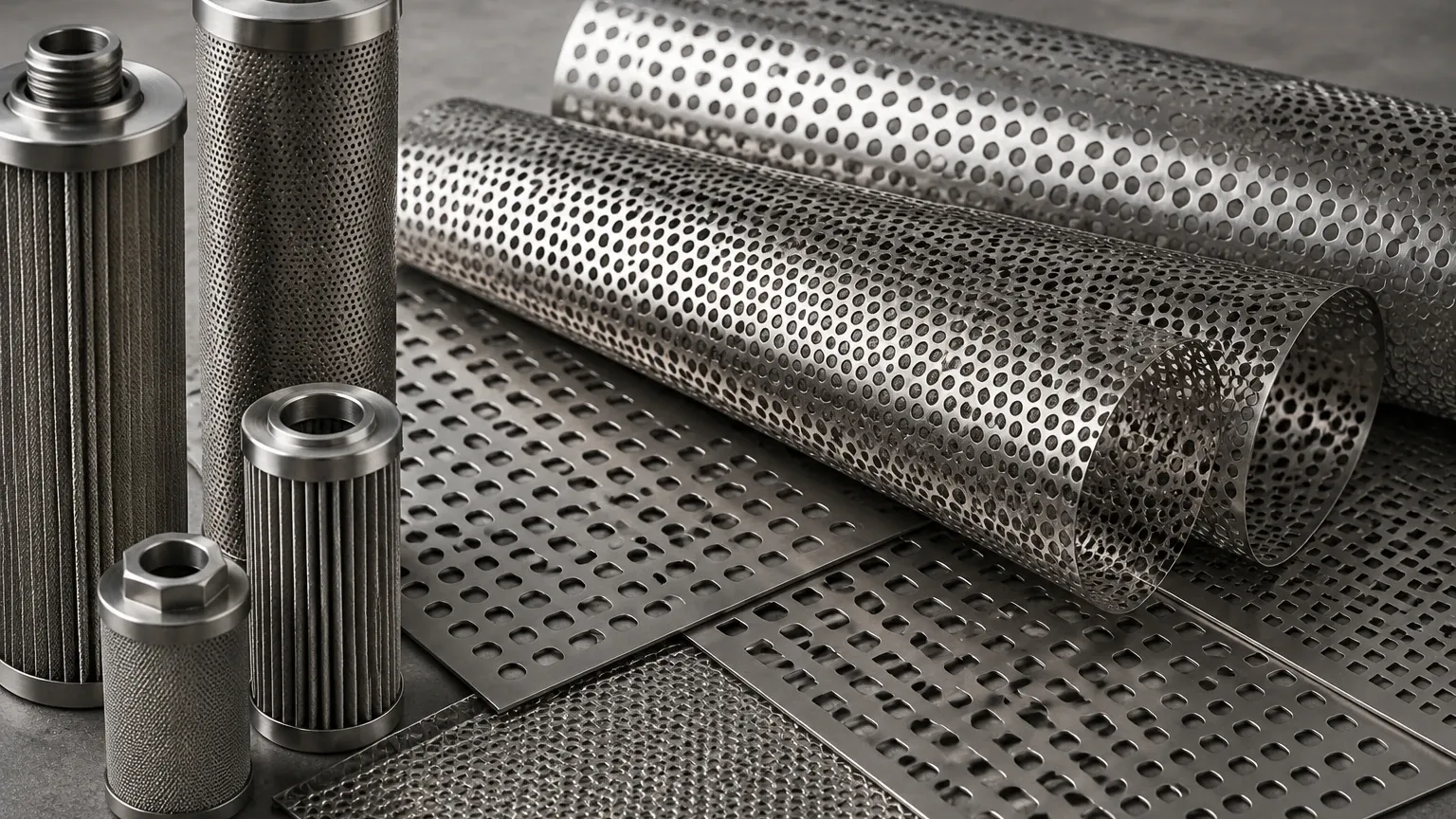
When specifying Perforated & Expanded Metal, engineers must consider the "ligament width"—the distance between the edges of adjacent holes. If the ligament is too thin relative to the material thickness, the sheet may tear during production or fail under the mechanical loads of a filtration system.
Calculating Open Area and Flow Dynamics
The most critical specification for a perforated filter is the "Open Area Percentage." This figure represents the ratio of the total area of the holes to the total area of the sheet. It is the primary factor determining the flow rate and the pressure drop (delta P) across the filter.
For a standard 60-degree staggered round hole pattern, the formula is:
Open Area % = (D² × 90.69) / P²
*(Where D is the hole diameter and P is the pitch)*
Engineers must find the "sweet spot" where the open area is high enough to allow efficient fluid flow but low enough to maintain the structural integrity of the filter cartridge. In high-pressure applications, such as hydraulic oil filtration, a lower open area with thicker ligaments is often necessary to prevent the perforated core from collapsing under the differential pressure.
Post-Production Processes and Quality Control
Once the perforation is complete, several secondary operations ensure the component is fit for industrial use.
1. Deburring: The punching process naturally leaves a small "burr" on the exit side of the hole. In filtration, these burrs can trap contaminants or damage secondary filter media (like wire mesh or paper). Mechanical brushing or electropolishing is used to achieve a smooth finish.
2. Annealing: For stainless steel components that undergo significant deformation, heat treatment (annealing) may be required to relieve internal stresses and restore corrosion resistance.
3. Slitting and Shearing: Perforated coils are often slit to specific widths or sheared into precise blanks for rolling into cylinders (filter cores).
4. Dimensional Inspection: Quality control teams use precision gauges and optical comparators to verify hole diameters, pitch accuracy, and margins (the unperforated areas along the edges of the sheet).
Selecting Perforated & Expanded Metal for Industrial Filtration
In many filtration designs, there is a choice between using perforated metal and expanded metal. While perforated metal is made by removing material, expanded metal is made by slitting and stretching the sheet simultaneously. Expanded metal results in no waste material and creates a 3D truss-like structure, which can be advantageous for certain structural supports.
However, perforated metal remains the preferred choice for precision filtration for several reasons:
* Predictable Flow: The circular or geometric holes provide a more consistent and calculable flow path than the diamond-shaped openings of expanded metal.
* Smooth Surface: Perforated metal can be leveled to a near-perfect flatness, making it easier to pleat or wrap with fine wire mesh.
* Customization: The ability to leave "blank" or unperforated margins is essential for welding the material into cylindrical filter cartridges.
When sourcing these components, it is vital to work with a manufacturer that understands the nuances of filtration engineering. Factors such as the direction of the stagger (parallel or perpendicular to the flow) and the choice of finishing can have a profound impact on the longevity of the filter.
For engineers designing custom filtration systems, the integration of high-quality Perforated & Expanded Metal ensures that the final product can withstand the rigors of chemical exposure, high temperatures, and mechanical stress. By understanding how is perforated metal made, technical professionals can make more informed decisions regarding tolerances and material specifications, ultimately leading to more reliable and efficient industrial processes.
