


Perforated Metal Open Area Calculator
In industrial filtration and structural engineering, the "open area" of a metal sheet is one of the most critical variables for determining performance. Whether designing a high-pressure hydraulic filter, a chemical processing strainer, or an architectural ventilation panel, engineers must precisely calculate the percentage of the sheet that is comprised of holes versus solid material. This calculation directly influences flow rates, pressure drop, particle retention, and the mechanical integrity of the component.
Using a perforated metal open area calculator allows technical teams to simulate different configurations before moving into the prototyping phase. Understanding the underlying mathematics and engineering trade-offs ensures that the final Perforated & Expanded Metal product meets the rigorous demands of industrial environments.
The Fundamental Role of Open Area in Industrial Filtration
Open area is defined as the ratio of the total area of the perforations to the total area of the sheet, usually expressed as a percentage. In the context of filtration, this value determines the "throughput" capacity of the filter element. A higher open area typically results in a lower pressure drop (ΔP), which is essential for maintaining system efficiency and reducing energy consumption in pumping or ventilation systems.
However, open area cannot be viewed in isolation. For manufacturers like Kaifil, the challenge lies in balancing high permeability with the structural requirements of the application. If the open area is too high, the remaining "bridge" (the metal between the holes) may become too narrow, leading to material fatigue, deformation under high pressure, or failure during the welding and fabrication process. Conversely, an open area that is too low may cause excessive resistance to flow, leading to premature clogging and increased maintenance cycles.
Understanding the Variables: Pitch, Diameter, and Pattern
To use a perforated metal open area calculator effectively, one must understand the three primary variables that dictate the result:
1. Hole Diameter (D): The actual size of the perforation. In industrial filtration, this is often determined by the size of the particles that need to be retained.
2. Pitch (P): The center-to-center distance between two adjacent holes. This is perhaps the most critical measurement, as it determines the density of the perforations.
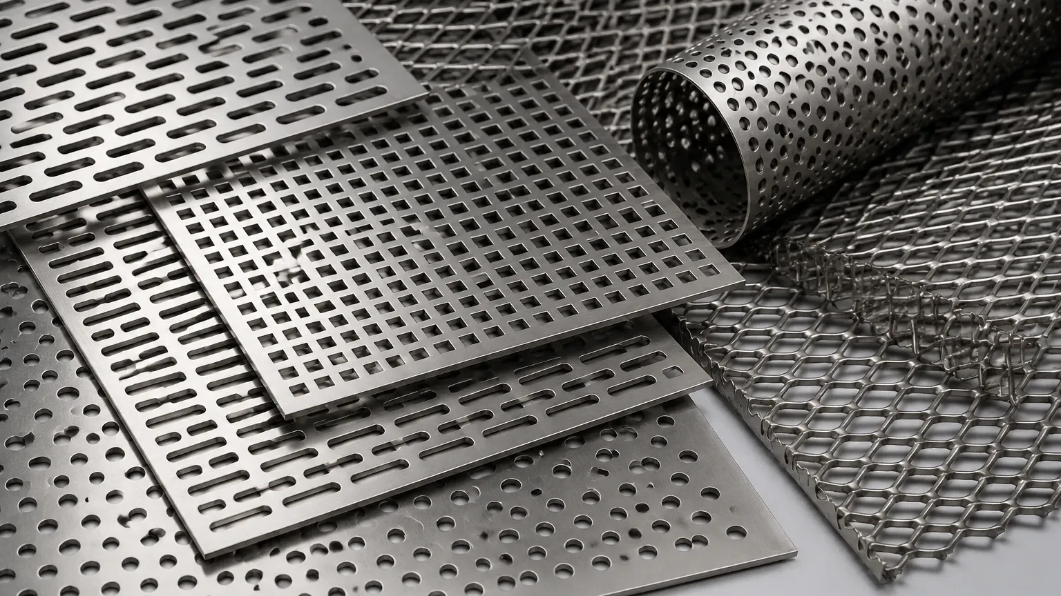
3. Pattern Arrangement: The geometric layout of the holes. The most common patterns are 60-degree staggered, 45-degree staggered, and straight-line (square) patterns.
60-Degree Staggered Pattern
The 60-degree staggered pattern is the industry standard for most industrial applications. It provides the highest degree of structural uniformity and the most efficient use of space, allowing for the highest possible open area without compromising the strength of the metal bridge.
Straight Line Pattern
In a straight-line or square pattern, the holes are aligned both horizontally and vertically. While easier to visualize, this pattern is generally weaker than staggered arrangements because it creates continuous "fail lines" where the metal is thin, making it more susceptible to bending or tearing under load.
Mathematical Formulas for Open Area Calculation
While a digital perforated metal open area calculator provides instant results, engineers often need to perform manual verifications to account for custom margins or non-standard hole shapes. Below are the standard formulas used for the most common perforation types.
Round Holes, 60-Degree Staggered
This is the most frequent calculation performed in industrial filtration design. The formula is:
Open Area % = (D² × 90.69) / P²
Where:
* D = Hole Diameter
* P = Center-to-Center Pitch
Round Holes, Straight Line
For patterns where holes are aligned in a grid:
Open Area % = (D² × 78.5) / P²
Square Holes, Straight Line
Square perforations are often used for high-flow applications where maximum open area is required and particle shape is uniform:
Open Area % = (S² × 100) / P²
Where:
* S = Side of the square hole
* P = Center-to-Center Pitch
Engineering Considerations: Open Area vs. Pressure Drop
One of the primary reasons engineers utilize a perforated metal open area calculator is to predict the pressure drop across a filter element. In fluid dynamics, the relationship between open area and pressure drop is non-linear. As the open area decreases, the velocity of the fluid passing through the holes increases, which in turn increases the turbulence and the resistance to flow.
In hydraulic and chemical processing applications, maintaining a low pressure drop is vital for protecting downstream components like pumps and valves. Engineers must also consider the "clogging factor." If a filter is designed with a 20% open area, and 10% of that area becomes obscured by debris, the pressure drop will spike significantly faster than it would on a filter with a 40% initial open area.
Kaifil’s technical team often recommends a higher initial open area for applications involving high-viscosity fluids or high-solids loading to extend the service life of the Perforated & Expanded Metal components.
The Impact of Material Selection on Perforation Limits
The physical properties of the metal being perforated impose limits on the maximum achievable open area. Stainless steel (304, 316L) is the preferred material for industrial filtration due to its corrosion resistance and mechanical strength. However, the thickness of the material (gauge) must be considered alongside the hole diameter.
As a general engineering rule of thumb, the hole diameter should not be smaller than the material thickness. For example, if you are using a 2mm thick stainless steel sheet, the minimum recommended hole diameter is also 2mm. Attempting to punch holes smaller than the material thickness significantly increases the risk of tool breakage and can lead to burrs or irregular hole shapes, which negatively impact filtration precision.
When using a perforated metal open area calculator, always cross-reference the results with the material gauge to ensure the design is manufacturable. High-performance alloys may require specialized CNC punching or laser cutting to achieve tight tolerances in thick sections.
Margins and Unfinished Areas: The "Effective" Open Area
A common mistake in procurement is calculating the open area based solely on the perforated pattern while ignoring the margins. In industrial filter cartridges, unperforated margins are required for welding, mounting, or structural reinforcement.
If a sheet has large solid borders, the "effective" open area of the entire component will be lower than the theoretical open area of the perforated section. When specifying requirements for Perforated & Expanded Metal, it is essential to provide the dimensions of the finished part and the required margin widths. This allows the manufacturer to calculate the total flow capacity accurately.
Selecting the Right Specification for Your Application
Choosing the correct configuration involves a multi-step evaluation process:
1. Define Particle Retention: Determine the maximum allowable particle size to set the hole diameter.
2. Calculate Required Flow Rate: Use the perforated metal open area calculator to find a pitch/diameter combination that provides the necessary throughput.
3. Assess Structural Load: Ensure the remaining bridge width is sufficient to withstand the operating pressure and mechanical stresses.
4. Consider Maintenance: Evaluate if the open area is sufficient to allow for cleaning or if the pattern is prone to permanent blinding.
For specialized OEM requirements, working with a manufacturer that understands the nuances of precision metal filtration is critical. Kaifil provides customized solutions where the perforation pattern is optimized for the specific fluid dynamics of the customer’s system, ensuring that the Perforated & Expanded Metal performs reliably under demanding conditions.
Conclusion: Precision in Perforation
The use of a perforated metal open area calculator is the first step in a sophisticated engineering process. By understanding the mathematical relationship between hole size, pitch, and pattern, and by accounting for material limitations and structural requirements, technical professionals can design filtration components that are both efficient and durable.
Whether you are developing a new pharmaceutical filtration system or upgrading a water treatment plant, the precision of your perforated metal specifications will dictate the long-term success of the installation. For those requiring high-performance stainless steel filtration components, focusing on the technical balance between open area and structural integrity is the key to optimized industrial performance.
