


Perforated Metal Chart
In industrial manufacturing and filtration engineering, a perforated metal chart serves as the fundamental reference for specifying material characteristics, hole patterns, and mechanical performance. For engineers and procurement professionals, understanding these charts is essential to ensuring that a component meets the rigorous demands of chemical processing, food production, or hydraulic systems. A well-interpreted chart allows for the precise balancing of open area, structural integrity, and filtration efficiency.
At Kaifil, we recognize that selecting the right perforation pattern is not merely a matter of aesthetics but a critical engineering decision. This guide breaks down the technical components of a perforated metal chart, the mathematical formulas governing open area, and the practical considerations necessary for specifying high-performance metal components.
Key Parameters in a Perforated Metal Chart
A standard perforated metal chart typically lists several variables that define the physical geometry of the sheet. Understanding these terms is the first step in communicating requirements to a manufacturer.
1. Hole Shape
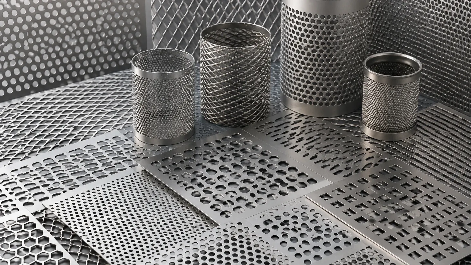
While round holes are the most common due to their structural stability and ease of manufacturing, charts also include square, slotted, hexagonal, and decorative patterns. In filtration, round holes are preferred for their uniform stress distribution.
2. Hole Diameter (D)
The hole diameter refers to the actual size of the opening punched into the metal. In precision filtration, this dimension determines the maximum particle size that can pass through the media.
3. Center Distance or Pitch (C/P)
The pitch is the distance from the center of one hole to the center of the adjacent hole. This measurement is critical because it determines the density of the holes on the sheet and, consequently, the percentage of open area.
4. Hole Arrangement (Pattern)
Most charts distinguish between staggered and straight-row patterns.
* 60-Degree Staggered: This is the industry standard. It provides the highest open area and the greatest structural strength because the holes are equidistant from one another.
* 45-Degree Staggered: An alternative used for specific directional flow requirements.
* Straight Line: Holes are aligned in both vertical and horizontal rows. This pattern is generally weaker than staggered arrangements and is often used for aesthetic or specific mechanical indexing applications.
Calculating the Percentage of Open Area
The "Open Area" is perhaps the most important value on a perforated metal chart. It represents the ratio of the total area of the holes to the total area of the sheet, expressed as a percentage. This value directly impacts flow rates, pressure drop, and the weight of the final component.
Round Hole, 60-Degree Staggered Pattern
The formula used to calculate the open area for the most common industrial pattern is:
Open Area % = (D² × 90.69) / C²
Where:
* D = Hole Diameter
* C = Center-to-Center Pitch
For example, if an engineer specifies a 2.0mm hole on a 4.0mm pitch, the open area would be approximately 22.6%. Increasing the hole size while keeping the pitch constant increases the open area but reduces the "bar" (the metal remaining between holes), which can compromise the sheet's rigidity.
Round Hole, Straight Pattern
For straight-row patterns, the formula is simpler:
Open Area % = (D² × 78.5) / (C₁ × C₂)
Where C₁ and C₂ are the horizontal and vertical pitches. Straight patterns typically offer lower open areas than staggered patterns for the same hole size.
Material Gauges and Thickness Standards
A perforated metal chart must be read in conjunction with material thickness, often referred to by gauge or in millimeters/inches. The relationship between hole diameter and material thickness is a primary constraint in the perforation process.
The 1-to-1 Rule
As a general engineering rule, the hole diameter should not be smaller than the material thickness. For instance, if you are using a 2mm thick stainless steel sheet, the minimum recommended hole diameter is typically 2mm. Attempting to punch holes smaller than the material thickness increases the risk of tool breakage and can lead to uneven hole edges or "burrs."
Material Selection
Kaifil specializes in stainless steel filtration solutions, utilizing grades such as 304, 316, and 316L.
* Grade 304: Suitable for general industrial use where corrosion resistance is required.
* Grade 316/316L: Preferred for pharmaceutical, food and beverage, and marine applications due to superior resistance to chlorides and acids.
When reviewing a Perforated & Expanded Metal chart, it is vital to confirm that the chosen material can withstand the mechanical stresses of the perforation process at the desired thickness.
Interpreting Hole Patterns and Pitch for Filtration
In filtration applications, the perforated metal often serves as a support structure for finer wire mesh or as a primary filter for coarse particles. The choice of pattern on the perforated metal chart affects how the fluid interacts with the filter.
Staggered vs. Straight for Flow Dynamics
A 60-degree staggered pattern is almost always recommended for filtration. Because the holes are more densely packed, the fluid encounters less resistance, leading to a lower pressure drop across the filter. In contrast, straight patterns create "dead zones" where material can accumulate, potentially leading to clogging or uneven wear.
The Importance of the "Bar"
The "bar" is the metal remaining between the holes. A perforated metal chart helps engineers calculate the bar width (Pitch minus Diameter). If the bar is too narrow, the sheet may warp during the punching process or fail under high-pressure hydraulic loads. For high-pressure applications, such as hydraulic filter cores, a wider bar and a lower open area may be necessary to prevent the cylinder from collapsing.
Engineering Considerations: Beyond the Chart
While a perforated metal chart provides the mathematical foundation, several real-world factors must be considered during the procurement phase.
1. Margins (Unperforated Areas)
Standard perforated sheets often come with "minimum margins" along the edges. However, for custom filter cartridges or precision components, engineers may require "finished margins" (where the perforation stops exactly at a certain point) or "no margins" (where the pattern is sheared through). Specifying this early prevents assembly issues during welding or housing integration.
2. Flatness and Leveling
The perforation process involves high-tonnage presses that can introduce internal stresses into the metal, causing it to curl or bow. Professional manufacturers like Kaifil use leveling rollers to ensure the finished sheet meets flatness tolerances required for automated assembly lines.
3. Surface Finish
For the food and pharmaceutical industries, the surface must be free of oil, burrs, and sharp edges. Post-perforation processes such as degreasing, deburring, and electropolishing are often required to meet hygiene standards.
Perforated vs. Expanded Metal: Which to Choose?
Engineers often compare perforated metal with expanded metal when reviewing technical charts. While both fall under the category of Perforated & Expanded Metal, they are manufactured differently.
* Perforated Metal: Created by punching holes out of a solid sheet. This results in precise hole sizes and shapes but generates material waste (the "slugs"). It offers better dimensional accuracy for filtration.
* Expanded Metal: Created by slitting and stretching the metal simultaneously. This process produces no waste and creates a diamond-shaped opening. Expanded metal is often more cost-effective for safety guards or walkways but lacks the precise aperture control required for high-end industrial filtration.
Customization and OEM Capabilities at Kaifil
Standard perforated metal charts are an excellent starting point, but many industrial applications require custom solutions that fall outside standard stock sizes. Kaifil provides comprehensive OEM services to bridge the gap between theoretical charts and functional components.
Custom Tooling
If a project requires a specific hole size or pitch not found on a standard chart, custom die sets can be engineered. This is common in specialized chemical processing where a specific flow coefficient must be maintained.
Secondary Processing
Beyond providing the perforated sheet, Kaifil offers value-added services including:
* Rolling and Welding: Transforming perforated sheets into filter cylinders or baskets.
* Pleating Support: Providing perforated metal as a rigid support layer for pleated filter cartridges.
* Material Certification: Providing full traceability for stainless steel grades to ensure compliance with industry regulations.
Conclusion: Making Informed Decisions
A perforated metal chart is more than a list of numbers; it is a roadmap for balancing performance, cost, and durability. By understanding the relationship between hole diameter, pitch, and open area, engineering teams can specify components that optimize flow while maintaining structural integrity.
When selecting a partner for your filtration needs, it is essential to work with a manufacturer that understands the technical nuances of these charts. Whether you require standard patterns for industrial strainers or custom-engineered components for complex hydraulic systems, Kaifil provides the expertise and manufacturing precision necessary to deliver reliable results.
For technical assistance or to discuss your specific requirements based on a perforated metal chart, visit our product page: Perforated & Expanded Metal.
