


Calculate Net Filtration Pressure Given the Following Values
In industrial filtration, precision is the difference between a high-efficiency process and a system failure. Engineers and technical procurement teams must look beyond simple flow rates to understand the mechanics of how fluids move through a medium. One of the most critical calculations in this domain is determining the net filtration pressure (NFP). This value represents the actual force driving fluid through a filter, accounting for various resisting pressures within the system.
To accurately calculate net filtration pressure given the following values—such as hydrostatic pressure, osmotic pressure, and system backpressure—one must understand the underlying physics of the specific application, whether it involves chemical processing, hydraulic systems, or high-purity pharmaceutical filtration. Kaifil, a leader in custom stainless steel filtration solutions, emphasizes that NFP is a cornerstone of filter sizing and lifecycle management.
Understanding the Fundamentals of Net Filtration Pressure
Net filtration pressure is the effective pressure gradient that forces a liquid or gas through a filter medium. While often discussed in the context of biological membranes (the Starling equation), the concept is equally vital in industrial liquid-solid separation and gas filtration. In these settings, NFP determines the flux—the volume of fluid passing through a unit area of the filter per unit of time.
For most industrial applications utilizing stainless steel wire mesh or sintered metal cartridges, the "net" pressure is closely related to the differential pressure ($ΔP$). However, in complex chemical or water treatment processes involving semi-permeable membranes or highly concentrated solutions, osmotic pressure gradients must also be subtracted from the mechanical pressure difference to find the true NFP.
Managing NFP is essential because it directly impacts the structural integrity of the filter element. If the required NFP exceeds the structural limits of a stainless steel mesh, the media may deform or bypass, leading to downstream contamination. Conversely, an NFP that is too low indicates an inefficient process or a filter that is prematurely blinded.
The Core Variables: What Values Do You Need?
To calculate net filtration pressure given the following values, you must first identify the specific parameters of your hydraulic circuit or process line. In a standard industrial filtration setup, the primary values required include:
1. Inlet Pressure ($P_{in}$): The total pressure of the fluid as it enters the filter housing.
2. Outlet Pressure ($P_{out}$): The pressure of the fluid after it has passed through the filter media.
3. Hydrostatic Pressure ($P_h$): The pressure exerted by the fluid due to gravity, which is particularly relevant in vertical filter towers or large-scale tanks.
4. Osmotic Pressure ($π$): In applications like desalination or fine chemical separation, the concentration of solutes creates a counter-pressure that opposes the mechanical flow.
By evaluating these variables, engineers can determine the actual work being done by the system pumps and the resistance offered by the filter media. For those seeking technical specifications on how different media types affect these variables, visiting the Kaifil Main Page offers a comprehensive overview of material capabilities.
Step-by-Step: How to Calculate Net Filtration Pressure Given the Following Values
The mathematical representation of NFP varies slightly depending on the complexity of the fluid. However, the general engineering formula used to calculate net filtration pressure given the following values is:
$$NFP = (P_{in} – P_{out}) – (π_{in} – π_{out})$$
In most mechanical filtration scenarios involving stainless steel cartridges or wire mesh, the osmotic pressure difference $(π_{in} – π_{out})$ is negligible (approaching zero). Therefore, the calculation simplifies to the differential pressure across the media:
$$NFP ≈ ΔP = P_{in} – P_{out}$$
Practical Example
Consider a hydraulic oil filtration system where the following values are provided:
* Inlet Pressure: 150 PSI
* Outlet Pressure: 142 PSI
* Osmotic Pressure: 0 PSI (standard for non-aqueous oils)
In this case, the NFP is simply $150 – 142 = 8$ PSI. This 8 PSI is the force overcoming the resistance of the clean stainless steel filter mesh. As the filter accumulates contaminants, the $P_{out}$ will drop, causing the NFP (and $ΔP$) to increase. When the NFP reaches a predetermined threshold (e.g., 25 PSI), the filter is considered fouled and requires cleaning or replacement.
Engineering Considerations for Stainless Steel Filter Media
When calculating NFP for custom industrial solutions, the physical properties of the filter media play a significant role. Stainless steel, favored for its durability and temperature resistance, behaves differently than polymer membranes.
Mesh Geometry and Permeability
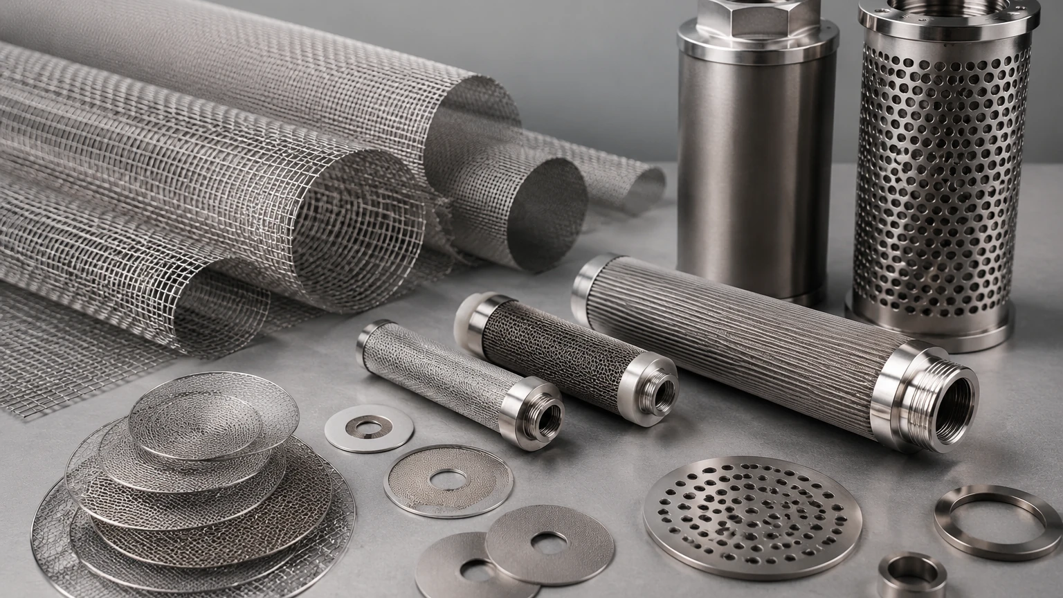
The weave pattern of a stainless steel wire mesh—whether it is plain weave, twilled weave, or Dutch weave—dictates the initial pressure drop. A denser weave provides finer filtration but results in a higher initial resistance, meaning a higher inlet pressure is required to maintain the same NFP and flow rate. Engineers must balance the required micron rating with the available system pressure.
Sintered Metal Components
For high-pressure applications, sintered metal filter cartridges are often used. These components consist of multiple layers of wire mesh or metal fibers fused together. The tortuous path created by sintering increases the resistance compared to a single layer of mesh. When you calculate net filtration pressure given the following values in a sintered system, you must account for the higher "clean" pressure drop inherent in the media's depth.
Factors Influencing Pressure Drop and NFP in Industrial Systems
Calculations are rarely static. Several dynamic factors can shift the values used to determine NFP during operation:
* Fluid Viscosity: Viscosity is highly temperature-dependent. In cold start-up conditions, oil or chemical resins are more viscous, leading to a much higher pressure drop across the filter. This reduces the NFP available for actual flow, often triggering bypass valves.
* Flow Velocity: According to Darcy’s Law, the pressure drop across a porous medium is proportional to the velocity of the fluid. Doubling the flow rate can more than double the pressure drop, significantly altering the NFP requirements.
* Contaminant Loading: As particles are trapped on the surface or within the depth of the mesh, the effective open area decreases. This increases the resistance, requiring the system to exert more pressure to maintain the NFP necessary for the target flow rate.
* Temperature: Beyond affecting viscosity, extreme temperatures can cause thermal expansion of the filter housing and the filter element itself, potentially altering the seal integrity or the pore size of the mesh.
Total Cost of Ownership and Replacement Cycles
Understanding how to calculate net filtration pressure given the following values is not just a theoretical exercise; it is a financial one. The NFP is a direct indicator of energy consumption. The higher the pressure drop required to push fluid through a filter, the harder the pumps must work, leading to higher electricity costs.
By monitoring NFP, maintenance teams can optimize replacement cycles. Replacing a filter too early wastes the remaining life of the media, while replacing it too late can lead to:
1. Pump Cavitation: If the filter is on the suction side and the NFP becomes too high, the pump may starve.
2. Media Collapse: Stainless steel is strong, but every mesh has a maximum differential pressure rating. Exceeding this can cause the pleats to collapse or the mesh to tear.
3. Decreased Product Quality: In food and beverage or pharmaceutical applications, a blinded filter can lead to inconsistent flow, affecting the residence time in heat exchangers or mixing tanks.
Kaifil’s engineering team assists clients in determining the optimal NFP thresholds for their specific hardware, ensuring that the total cost of ownership remains low through durable, cleanable stainless steel components.
Customization and Selection Methods
Selecting the right filter involves more than picking a micron rating from a catalog. It requires a holistic view of the system's pressure profile. When consulting with a manufacturer like Kaifil, engineers should be prepared to provide the values discussed above to ensure the custom filter is fit for purpose.
Customization options include:
* Pleated vs. Cylindrical: Pleating increases the surface area, which reduces the velocity of the fluid through the mesh. This lower velocity results in a lower pressure drop and a more stable NFP over the life of the filter.
* Reinforcement Layers: For high-NFP applications, a coarse support mesh can be added to the fine filtration mesh to prevent deformation under high differential pressure.
* Material Grades: Selecting between 304, 316L, or specialized alloys like Hastelloy depends on the chemical compatibility and the potential for corrosion, which could otherwise pit the mesh and change its filtration characteristics.
Conclusion: Achieving Optimized Filtration Performance
Accurately determining the pressure dynamics within a system is the first step toward process optimization. When you calculate net filtration pressure given the following values, you gain a clear picture of the efficiency and health of your filtration stage. Whether you are managing a hydraulic system or a complex chemical reactor, the NFP serves as your primary diagnostic tool.
By partnering with a specialist manufacturer, you can translate these calculations into high-performance hardware. For detailed technical support, material data sheets, and customized engineering solutions, professionals are encouraged to explore the resources available on the Kaifil Main Page. From initial design to the final production of precision metal filter components, understanding the pressure requirements ensures that your industrial filtration system operates at peak reliability and cost-effectiveness.
Download Calculate Net Filtration Pressure Given the Following Values as a PDF
