


Expanded Metal Dwg
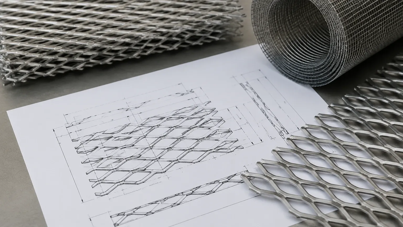
In the realm of industrial design and mechanical engineering, the transition from a conceptual model to a physical component requires high-precision technical documentation. For engineers developing filtration systems, structural supports, or protective enclosures, an expanded metal dwg (Drawing) file serves as the foundational blueprint. These CAD files are essential for defining the geometric parameters, material thickness, and structural integrity of expanded metal mesh before it enters the manufacturing phase.
At Kaifil, we understand that a well-executed drawing is the difference between a high-performance filtration component and a part that fails to meet tolerances. As a specialist in custom stainless steel filtration solutions, we rely on precise technical data to manufacture Perforated & Expanded Metal products that meet the rigorous demands of chemical processing, water treatment, and hydraulic applications.
Understanding Expanded Metal Specifications in CAD Environments
When an engineer searches for or creates an expanded metal dwg, they are looking for more than just a visual pattern. The drawing must accurately represent the unique geometry created by the expanding process. Unlike perforated metal, which is created by punching holes and removing material, expanded metal is produced by shearing and stretching a solid sheet. This process creates a diamond-shaped pattern without any material waste, but it introduces complex three-dimensional characteristics that must be captured in the CAD model.
Key Geometric Parameters
To ensure the drawing translates correctly to production, several key metrics must be defined within the DWG file:
* LWD (Long Way of Design): The distance from the center of one joint to the center of the next joint across the long diamond dimension.
* SWD (Short Way of Design): The distance from the center of one joint to the center of the next joint across the short diamond dimension.
* LWO (Long Way of Opening): The actual width of the opening.
* SWO (Short Way of Opening): The actual height of the opening.
* Strand Width: The amount of metal between the openings.
* Strand Thickness: The gauge of the original base material.
In an expanded metal dwg, these dimensions determine the "open area" percentage, which is a critical calculation for filtration efficiency and flow rates. If the drawing does not account for the strand angle or the thickness of the joints (bonds), the resulting airflow or fluid dynamics simulations will be inaccurate.
The Role of DWG Files in Industrial Filtration Design
In industrial filtration, expanded metal often serves as a support structure for finer wire mesh or as a primary coarse filter. The precision of the CAD file ensures that the filter cartridge or panel fits perfectly within its housing.
Structural Support and Pleating
When designing stainless steel filter cartridges, expanded metal is frequently used as an inner core or outer guard. The DWG file allows engineers to calculate the collapse pressure of the core. By modeling the expanded metal in 3D, designers can simulate how the mesh will react under high-pressure hydraulic flows. If the LWD and SWD are not optimized in the drawing, the core may buckle, leading to system failure.
Fluid Dynamics and Pressure Drop
For engineers in the chemical and pharmaceutical industries, the pressure drop across a filter is a primary concern. An accurate expanded metal dwg allows for Computational Fluid Dynamics (CFD) analysis. By providing the exact geometry of the strands and the angle at which they sit (in raised expanded metal), designers can predict turbulence and flow resistance. This level of detail is necessary to ensure that the filtration system does not consume excessive energy or cause cavitation in pumps.
Evaluating Expanded Metal: Raised vs. Flattened
One of the most important distinctions to make in a technical drawing is whether the material is "Raised" (Standard) or "Flattened." This choice significantly impacts the physical dimensions and performance of the final product.
Raised Expanded Metal
In its standard form, expanded metal comes off the machine with the strands set at an angle to the plane of the sheet. This creates a three-dimensional texture that provides excellent grip and strength-to-weight ratios. In a DWG file, this requires a more complex 3D model to represent the depth of the sheet. Raised expanded metal is often preferred for mechanical protection and coarse filtration where surface area is a secondary concern to structural rigidity.
Flattened Expanded Metal
Flattened expanded metal is produced by passing the standard expanded sheet through a cold-roll reducing mill. This process flattens the strands and bonds into a single plane, reducing the overall thickness and making the surface smooth. From a CAD perspective, a flattened expanded metal dwg is simpler to integrate into assemblies where space is limited, such as thin-profile filter leaves or decorative architectural panels. Engineers must confirm whether their drawing specifies the thickness of the flattened sheet or the original gauge, as the rolling process slightly increases the overall dimensions of the LWD and SWD.
Material Selection and Engineering Considerations
While the DWG file defines the shape, the material specification defines the performance environment. Kaifil specializes in stainless steel alloys, which are the gold standard for industrial filtration due to their corrosion resistance and thermal stability.
Stainless Steel 304 vs. 316L
* Grade 304: Suitable for general industrial use, providing good corrosion resistance and excellent forming properties. It is commonly used in food processing and general water filtration.
* Grade 316L: Contains molybdenum, which provides superior resistance to chlorides and pitting. This is the preferred specification for marine environments, pharmaceutical manufacturing, and aggressive chemical processing.
When preparing an expanded metal dwg for a custom project, engineers should annotate the drawing with the specific alloy and any required certifications (such as FDA compliance for food-grade applications). The choice of material also affects the manufacturing tolerances; for instance, harder alloys may have slightly different spring-back characteristics during the expanding process, which must be accounted for in precision designs.
Common Risks in CAD Modeling for Expanded Metal
Designing with expanded metal presents unique challenges that can lead to manufacturing delays if not addressed in the initial drawing phase.
File Complexity and System Performance
One common issue is the sheer complexity of a mesh pattern. A large panel of expanded metal with thousands of small diamond openings can significantly slow down CAD software performance. To mitigate this, many engineers use a "representative area" in their expanded metal dwg—modeling a small section in high detail while using a simplified texture or hatch pattern for the remainder of the part. However, it is vital that the boundary conditions and edge treatments are clearly defined to ensure the panel can be cut and framed correctly.
Edge Conditions and Framing
How the expanded metal terminates at the edges is a critical detail. If the drawing does not specify "random shear" versus "bond shear," the manufacturer may produce a part that is difficult to weld into a frame.
* Bond Shear: The cut is made through the joints, resulting in a closed diamond edge that is safer to handle and easier to weld.
* Random Shear: The cut is made anywhere along the pattern, which may leave sharp, jagged points.
Ensuring these details are present in the DWG prevents misalignment during the assembly of complex filtration units.
Customization and OEM Capabilities at Kaifil
At Kaifil, we bridge the gap between digital design and industrial reality. We work closely with engineering teams to interpret their expanded metal dwg files and provide feedback on manufacturability. Our facility is equipped to handle custom requests that go beyond standard catalog sizes.
Tailored Filtration Solutions
Whether you require a specific open area for a unique chemical process or a reinforced structure for high-pressure hydraulics, our team can customize the expansion ratio and strand width. We often assist clients in optimizing their drawings to reduce material waste and improve the total cost of ownership. By selecting the right combination of Perforated & Expanded Metal, we help our partners achieve durable and cost-effective filtration performance.
Quality Assurance and Tolerance Control
Every project begins with a review of the technical specifications. We ensure that the physical product matches the CAD model within strict industrial tolerances. This is particularly important for OEM components where the expanded metal must integrate seamlessly into larger mechanical assemblies. Our commitment to quality means that the dimensions specified in your DWG are the dimensions you receive in the final product.
Conclusion: From Drawing to Performance
An expanded metal dwg is more than a file; it is a communication tool that ensures engineering intent is translated into a functional industrial component. By carefully considering the LWD/SWD ratios, material grades, and edge treatments during the design phase, engineers can optimize their filtration systems for longevity and efficiency.
For those seeking reliable, high-performance filtration components, partnering with a manufacturer that understands the technical nuances of expanded metal is essential. Kaifil provides the engineering expertise and manufacturing precision needed to turn complex CAD designs into dependable filtration solutions. Whether you are in the early stages of design or ready for full-scale OEM production, focusing on the technical accuracy of your metal specifications is the first step toward optimized industrial performance.
