


How to Make Perforated Metal in Sketchup
In industrial design and filtration engineering, visualizing the final product is a critical step before moving to physical prototyping or full-scale production. Perforated metal is a staple in the manufacturing of filter cartridges, architectural screens, and industrial strainers. When using SketchUp for these designs, engineers often face a challenge: how to represent thousands of precision-punched holes without compromising software performance or sacrificing the technical accuracy required for manufacturing specifications.
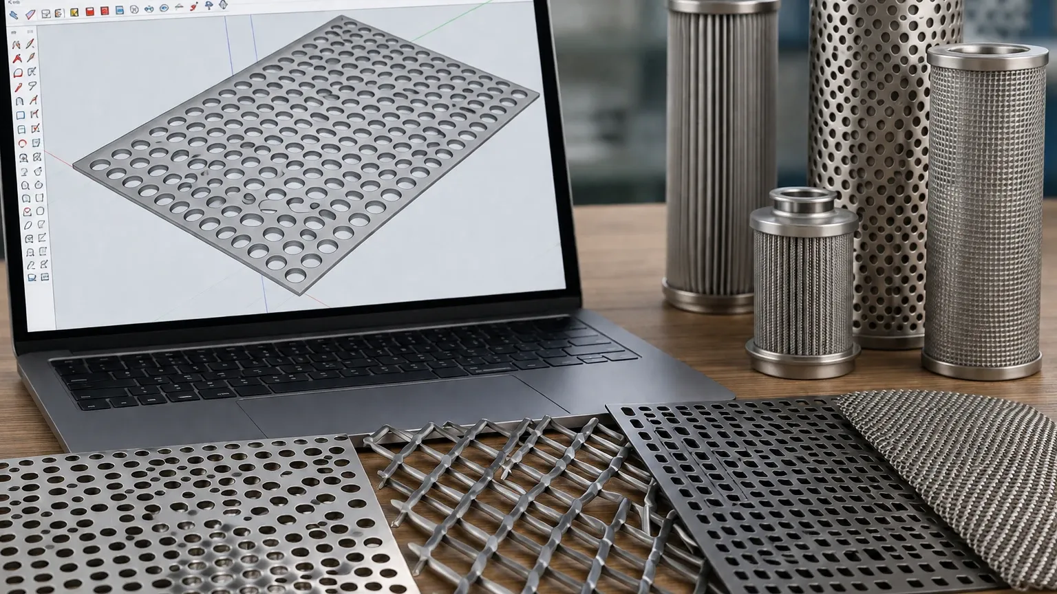
Whether you are designing a custom stainless steel filter housing or a protective industrial guard, understanding the different methods for creating Perforated & Expanded Metal in SketchUp is essential. This guide covers three primary techniques—texture mapping, geometry modeling, and extension-based generation—while highlighting the engineering considerations necessary to transition from a digital model to a high-performance filtration component.
1. The Texture Mapping Method: Efficiency for Large-Scale Models
For many industrial applications, particularly when modeling large filtration systems or architectural facades, modeling every individual hole as 3D geometry is unnecessary and computationally expensive. Texture mapping allows you to represent perforated metal using a 2D image with an alpha channel (transparency).
When to Use Textures
This method is ideal for preliminary design phases, assembly layouts, and any scenario where the specific 3D edge of each hole does not impact the mechanical simulation. It keeps the file size small and the viewport responsive.
Step-by-Step Texture Application
1. Create or Source a High-Resolution PNG: You need a tileable image of the hole pattern (e.g., 60-degree staggered round holes). The "holes" must be transparent, and the "metal" must be opaque.
2. Import as Material: In SketchUp, go to the Materials browser and create a new material. Import your PNG as the texture.
3. Apply and Scale: Paint the material onto your surface. Use the "Texture > Position" tool to scale the pattern so the hole diameter and pitch match your engineering requirements (e.g., a 2mm hole with a 4mm pitch).
4. Enable Transparency: Ensure your style settings allow for transparency so you can see through the "holes" to the components behind the screen.
2. The Geometry Modeling Method: Precision for Manufacturing
When the model is intended for CNC laser cutting, waterjetting, or detailed component analysis, you must model the actual physical voids in the metal. This is the most accurate way to represent Perforated & Expanded Metal but requires careful management of SketchUp’s geometry engine.
Creating a Staggered Hole Pattern
Most industrial filters use a 60-degree staggered pattern because it offers the highest open area and structural integrity. To model this:
1. Draw the Base Plate: Create a rectangle representing the outer dimensions of your sheet and extrude it to the required thickness (e.g., 1.5mm for a standard stainless steel filter sleeve).
2. Model a Single Hole: Draw a circle on the surface. Use the "Push/Pull" tool to cut the hole through the thickness.
3. Create a Component: Select the hole geometry and turn it into a component. This is vital; if you need to change the hole diameter later, editing one component will update thousands of instances.
4. Array the Pattern: Use the "Move" tool combined with the "Ctrl" key (copy) to create a linear array. Then, offset the second row by half the pitch to create the staggered effect. Use the "x" or "/" commands in the measurements box to multiply the copies across the plate.
5. Intersect Faces: If you are working with complex curved surfaces (like a cylindrical filter cartridge), draw the flat perforated pattern first and then use a plugin like "Shape Bender" or the native "Intersect Faces" command to wrap or cut the pattern into the 3D form.
3. Using Extensions for Automated Generation
Manually arraying thousands of holes can be prone to error. Several SketchUp extensions are designed specifically to automate the creation of perforated patterns. Tools like *S4U Panel* or specific *Perforated Metal* scripts allow users to define parameters such as hole diameter, center-to-center distance (pitch), and margins.
Using an extension ensures that the "margins" (the solid metal borders around the perforated area) are maintained. In filtration manufacturing, margins are critical for welding the mesh or perforated sheet into a cylinder or frame without damaging the hole pattern.
4. Engineering Considerations: From Model to Production
While SketchUp helps visualize the product, several technical factors must be confirmed before the design is ready for production at a facility like Kaifil. Engineers must look beyond the visual representation to the mechanical performance of the material.
Open Area Calculations
The "Open Area" is the percentage of the sheet that is comprised of holes. This directly impacts flow rate and pressure drop in filtration applications. For a standard 60-degree staggered round hole pattern, the formula is:
Open Area % = (D² × 90.69) / P²
* D: Hole Diameter
* P: Pitch (Center-to-center distance)
If your SketchUp model shows a 50% open area but your hydraulic calculations require 60%, the model must be adjusted by increasing hole diameter or decreasing pitch before finalizing the specification.
Material Selection and Thickness
In SketchUp, it is easy to draw a 0.5mm thick wall, but in industrial filtration, the thickness must be balanced against the hole diameter. A general rule of thumb in perforated metal manufacturing is that the hole diameter should not be smaller than the material thickness. For example, if you are using 2mm thick 316L stainless steel, the minimum reliable hole diameter is typically 2mm. Attempting to punch smaller holes can lead to tool breakage and increased production costs.
Edge Margins and Dead Zones
When modeling a filter cartridge, remember to include "dead zones" or solid margins where the metal will be welded. A continuous pattern of holes up to the very edge of a sheet makes longitudinal welding difficult and can weaken the structural integrity of the filter. In your SketchUp model, define these solid borders clearly—usually 10mm to 20mm depending on the welding method (TIG, Plasma, or Laser welding).
5. Avoiding Common Modeling Risks
Modeling perforated metal can lead to significant software instability if handled incorrectly. To maintain a functional workflow, consider the following risks:
* Polygon Overload: A single circular hole in SketchUp defaults to 24 segments. If you have 5,000 holes, that is 120,000 edges just for the holes. Reduce the segment count of your circles to 6 or 8 for small holes; at a distance, they will still appear round but will significantly reduce the polygon count.
* Nested Components: Always use components instead of groups for the hole geometry. This allows SketchUp to use hardware instancing, which is much more efficient for the GPU to render.
* Layer Management: Keep your perforated geometry on a separate layer/tag. Turn this layer off while working on other parts of the assembly to keep the model fast.
6. Transitioning to Custom Filtration Solutions
Once the SketchUp model has helped you finalize the dimensions and pattern requirements, the next step is selecting the right manufacturing partner to realize the design. Industrial filtration requires high precision, particularly when the perforated metal serves as the inner core or outer support for fine wire mesh filters.
At Kaifil, we specialize in converting these technical requirements into durable hardware. Whether your application involves high-pressure hydraulic systems, chemical processing, or food-grade water treatment, the choice of perforated pattern and material grade (such as SS304, SS316, or Duplex steel) is paramount.
Before finalizing your purchase or production run, engineers should confirm:
1. Dimensional Tolerances: Ensure the SketchUp model accounts for the tolerances required for the final assembly.
2. Deburring Requirements: Punched holes often have a "burr" side. For pharmaceutical or food applications, specify a deburring process to ensure a smooth, cleanable surface.
3. Flatness Specifications: Large perforated sheets can warp during the punching process. Confirm if leveling is required for your specific application.
Conclusion
Creating perforated metal in SketchUp is a balance between visual representation and engineering accuracy. By using textures for broad layouts and precision geometry for component-level design, you can create effective models that facilitate better communication between design teams and manufacturers.
For professional-grade filtration components that require exact hole patterns and robust material performance, it is essential to work with a manufacturer that understands the nuances of metal perforation. Review product options and application support to see how custom perforated solutions can be integrated into your next industrial project.
