


Perforated Metal 3d
In modern industrial engineering, the selection of filtration components is no longer limited to two-dimensional specifications. As systems become more complex, the integration of Perforated & Expanded Metal requires a deeper understanding of spatial dynamics, fluid flow, and structural integrity. The term "perforated metal 3d" refers to two critical aspects of industrial design: the digital modeling of perforated components within complex assemblies and the physical three-dimensional characteristics of expanded metal structures used in filtration and support.
For engineers and procurement teams, mastering these concepts is essential for ensuring that filtration media perform reliably under high-pressure, corrosive, or high-temperature environments. This guide examines the technical nuances of Perforated & Expanded Metal from an engineering perspective, focusing on how 3D considerations influence selection, performance, and long-term durability.
The Role of Perforated & Expanded Metal in Industrial Filtration
Perforated and expanded metals serve as the backbone for many industrial filtration systems. While they can act as primary filters for coarse particles, they are more frequently utilized as support structures for finer wire mesh or as protective outer cages for filter cartridges.
Perforated Metal
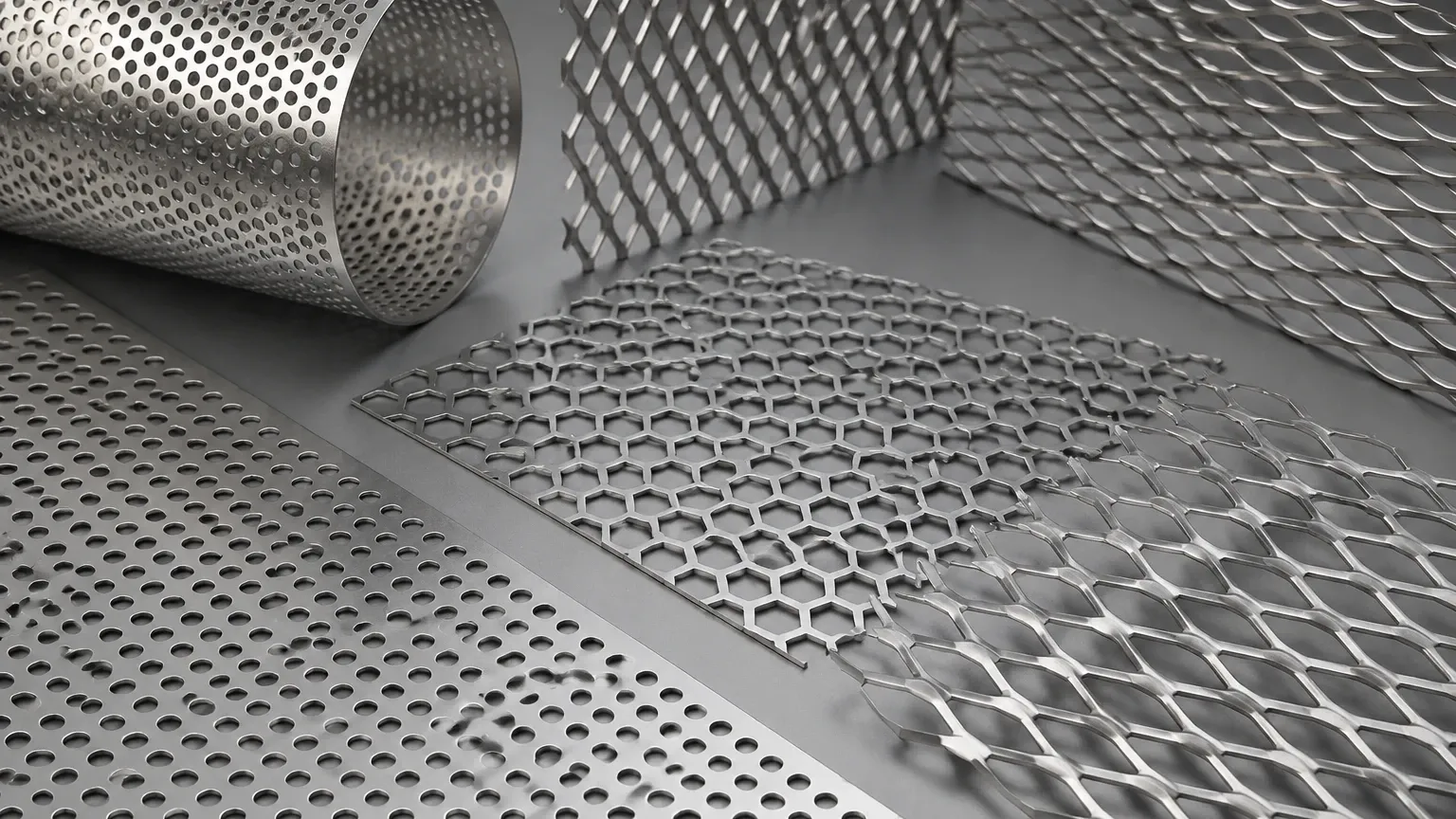
Perforated metal is produced by mechanically punching or laser-cutting holes into a solid metal sheet. This process allows for precise control over hole diameter, pitch, and pattern. In a 3D engineering context, the thickness of the sheet relative to the hole size creates a "tunnel" effect that can influence flow resistance and turbulence.
Expanded Metal
Unlike perforated metal, expanded metal is manufactured by simultaneously slitting and stretching the material. This process creates a diamond-shaped pattern without any material waste. The resulting structure is inherently three-dimensional; the strands are set at an angle to the plane of the sheet, providing a high strength-to-weight ratio and unique flow characteristics that differ significantly from flat perforated sheets.
Understanding Perforated Metal 3d: Digital Modeling and Physical Geometry
When engineers search for "perforated metal 3d," they are typically addressing the challenges of integrating these components into CAD (Computer-Aided Design) environments or analyzing the physical depth of the material.
Digital 3D Modeling for Engineering Integration
In complex industrial machinery, such as hydraulic systems or chemical reactors, every millimeter of space is accounted for. Utilizing a 3D model of a perforated component allows engineers to:
* Simulate Fluid Dynamics (CFD): By using a 3D representation, engineers can simulate how fluids move through the apertures. This helps in identifying potential pressure drops or areas of stagnation that could lead to sediment buildup.
* Verify Interference and Fit: 3D modeling ensures that the filter cartridge or support cage fits perfectly within the housing, accounting for tolerances in sheet thickness and weld seams.
* Analyze Structural Stress: Finite Element Analysis (FEA) on a 3D model helps determine if the perforated pattern can withstand the mechanical loads and pressure differentials expected during operation.
Physical 3D Characteristics of Expanded Metal
While perforated metal is generally flat (unless rolled into a cylinder), expanded metal is naturally three-dimensional. The "raised" version of expanded metal features strands that are tilted. This 3D geometry provides:
* Enhanced Surface Area: The angled strands increase the total surface area available for contact, which can be beneficial in certain catalytic or heat-exchange applications.
* Directional Flow Control: The orientation of the diamond openings can be used to deflect or direct fluid flow, a feature often utilized in specialized intake screens.
* Mechanical Grip: The 3D texture provides excellent mechanical bonding properties if the metal is used as a substrate for coatings or composite materials.
Technical Selection Criteria for Custom Metal Filtration
Selecting the right Perforated & Expanded Metal requires a balance of several technical parameters. Engineers must look beyond simple hole sizes and consider the following criteria to ensure application compatibility.
Open Area Calculations
The percentage of open area is the most critical factor for flow rate and pressure drop. For perforated metal with a 60-degree staggered round hole pattern, the formula is:
Open Area % = (D² × 90.69) / P²
*(Where D = Hole Diameter and P = Pitch)*
In a 3D system design, the open area must be sufficient to prevent excessive backpressure while maintaining the structural integrity of the filter element. If the open area is too high, the material may deform under the weight of the filtered media or the force of the fluid.
Hole Pattern and Orientation
* Staggered Patterns: These provide the highest open area and are the standard for most filtration supports.
* Straight Row Patterns: Used when specific directional strength is required, though they generally offer lower open area.
* Custom Geometric Apertures: For specialized 3D modeling requirements, square, hexagonal, or slotted holes can be engineered to meet specific particle retention needs.
Material Selection and Chemical Compatibility
The environment in which the filter operates dictates the material choice. Kaifil specializes in stainless steel solutions, which are preferred in industrial B2B applications for their longevity and resistance.
1. Stainless Steel 304: The standard for general industrial use, offering good corrosion resistance and excellent formability for 3D shapes.
2. Stainless Steel 316/316L: Contains molybdenum, providing superior resistance to chlorides and acids. This is the preferred choice for pharmaceutical and marine applications.
3. Duplex Stainless Steels: Used in high-stress environments where both high strength and extreme corrosion resistance are required.
4. Specialty Alloys: For high-temperature applications (e.g., exhaust filtration), alloys like Inconel or Monel may be used in perforated forms.
Performance Evaluation and Structural Integrity
In many industrial applications, the perforated metal acts as a "center tube" or "outer wrap" for a filter cartridge. In these 3D configurations, the collapse strength is a vital metric.
Collapse Pressure
Engineers must confirm the maximum pressure differential the component can withstand before deforming. This is influenced by the sheet thickness, the diameter of the finished cylinder, and the specific perforation pattern. A 3D analysis of the cylindrical geometry often reveals that a thicker gauge is necessary for the inner support than for the outer protective wrap.
Filtration Accuracy vs. Support Capability
While the perforated metal provides the 3D structure, it often lacks the fine filtration accuracy required for sub-micron particles. In these cases, it is paired with multi-layer wire mesh. The 3D design must ensure that the mesh is fully supported across the perforated surface to prevent "bagging" or tearing of the fine mesh under pressure.
Common Risks in Procurement and Quality Verification
When sourcing Perforated & Expanded Metal, purchasing teams often encounter risks that can lead to system failure or increased maintenance costs. Addressing these during the specification phase is critical.
* Burrs and Sharp Edges: In perforated metal, the punching process can leave burrs on the "downside" of the sheet. In filtration, these burrs can damage delicate filter membranes or shed metallic particles into the downstream flow. Specifying de-burring or electropolishing is a common solution.
* Inconsistent Pitch: If the pitch (distance between hole centers) is inconsistent, the open area will vary across the sheet, leading to uneven flow distribution and localized stress points.
* Material Substitution: Lower-grade stainless steel may be substituted to reduce costs, leading to premature corrosion. Engineers should require material test reports (MTRs) to verify the chemical composition of the alloy.
* Flatness and Camber: For 3D assembly, the flatness of the starting sheet is essential. If the sheet has significant camber (curvature), it will be difficult to roll into a perfect cylinder, leading to gaps at the weld seam.
Customization and OEM Capabilities
Every industrial application has unique constraints. Standard off-the-shelf perforated sheets rarely meet the precise needs of high-performance filtration systems. Kaifil provides customized solutions that bridge the gap between 3D design and physical production.
Tailored Margins
In many 3D filter designs, "blank" or unperforated margins are required for welding or mounting. Custom manufacturing allows for the precise placement of these margins, ensuring that the structural integrity of the weld is not compromised by holes.
Precision Forming
Beyond simple flat sheets, perforated metal can be formed into cones, cylinders, or multi-faceted 3D shapes. Precision forming ensures that the filtration media maintains its geometric tolerances, which is essential for automated cleaning systems or backwashing filters.
Maintenance and Total Cost of Ownership
While the initial purchase price is a factor, the total cost of ownership (TCO) is driven by durability and cleanability.
* Cleanability: Perforated metal is generally easier to clean than woven mesh due to its smooth surface. In 3D modeled systems, the flow paths are designed to be accessible for CIP (Clean-In-Place) systems.
* Replacement Cycles: High-quality stainless steel perforated components can last for years, even in demanding environments. Choosing the correct 3D thickness and material grade significantly extends the time between replacements.
* Recyclability: Stainless steel is 100% recyclable, which is an increasingly important consideration for industrial sustainability goals.
Conclusion: Making Informed Engineering Decisions
Integrating Perforated & Expanded Metal into industrial systems requires more than just picking a part number from a catalog. It involves a comprehensive understanding of how the "perforated metal 3d" geometry interacts with the process fluid, the mechanical stresses of the system, and the chemical environment.
By focusing on accurate 3D modeling during the design phase and specifying high-quality materials and manufacturing tolerances, engineers can ensure that their filtration solutions provide reliable, long-term performance. Whether you are designing a high-pressure hydraulic filter or a large-scale chemical strainer, the structural and functional properties of these metal components are fundamental to system success.
For those seeking technical support or custom-engineered components, it is recommended to work with manufacturers who understand the complexities of industrial filtration and can provide the necessary documentation and precision to meet demanding specifications.
