


Perforated Metal Hatch Autocad
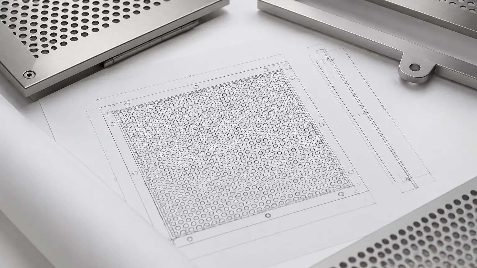
In the realm of industrial design and architectural engineering, the precise representation of materials is critical for both aesthetic visualization and functional performance. When designing filtration systems, acoustic panels, or structural screens, engineers frequently utilize Computer-Aided Design (CAD) software to define specifications. The term "perforated metal hatch autocad" refers to the specific methods and digital patterns used within AutoCAD to represent perforated or expanded metal sheets.
For a manufacturer like Kaifil, which specializes in high-precision stainless steel filtration solutions, the transition from a CAD drawing to a physical component requires a deep understanding of how digital hatches translate into manufacturing parameters. This article explores the technical considerations of specifying perforated metal in CAD, the engineering math behind the patterns, and the material factors that influence the final product's performance.
The Role of Digital Drafting in Perforated Metal Specification
AutoCAD serves as the primary bridge between an engineer’s conceptual design and the factory floor. When a project requires Perforated & Expanded Metal, the drawing must convey more than just a visual texture. It must communicate hole diameter, pitch, orientation, and margins.
In many architectural or simple mechanical drawings, a "hatch" is used to fill a closed boundary with a pattern. However, for industrial filtration and heavy-duty industrial applications, a standard hatch often lacks the precision required for CNC punching or laser cutting. Engineers must decide whether to use a representative hatch for visual clarity or to create a detailed geometric array that reflects the actual physical dimensions of the holes.
Using a perforated metal hatch autocad pattern allows designers to quickly fill large areas of a drawing without significantly increasing the file size. However, the scale of the hatch must be meticulously calibrated to ensure that the visual density on the screen matches the calculated "open area" required for the application, such as airflow in a server room or fluid throughput in a chemical strainer.
Technical Implementation: Managing Perforated Metal Hatch in AutoCAD
Standard AutoCAD installations come with a library of hatch patterns (stored in .pat files), such as `ANSI37` or `HONEY`, which can sometimes mimic perforated patterns. However, these are often insufficient for professional engineering standards.
Custom Hatch Patterns vs. Geometric Arrays
For high-precision components, engineers often develop custom .pat files that define the exact staggered or straight-line centers of the perforations. A custom hatch ensures that as the boundary of a component changes, the pattern remains consistent.
When the goal is manufacturing a custom filter cartridge, a simple hatch is usually replaced by a "Block" or an "Array." This is because the manufacturer needs to know the exact placement of the first and last holes relative to the edges (margins). If a hatch is used merely for a 2D layout, the engineer must supplement the drawing with a detailed technical table specifying:
* Hole Shape: Round, square, slotted, or hexagonal.
* Hole Arrangement: 60-degree staggered (most common for strength), 45-degree staggered, or straight row.
* Hole Diameter (D): The actual size of the opening.
* Pitch (P): The distance from the center of one hole to the center of the next.
Geometric Parameters and Open Area Calculations
The most critical technical data derived from a perforated metal design is the "Open Area Percentage." This figure determines the efficiency of the filter and the pressure drop across the medium. When specifying Perforated & Expanded Metal, the open area is calculated based on the geometry represented in the CAD hatch.
For a standard 60-degree staggered round hole pattern—the industry standard for industrial filtration—the formula used is:
Open Area % = (D² × 90.69) / P²
Where:
* D = Hole Diameter
* P = Pitch
If the CAD drawing uses a perforated metal hatch autocad pattern that is not to scale, the resulting physical product may fail to meet the hydraulic or pneumatic requirements of the system. For instance, in hydraulic filtration, a slight deviation in the pitch can lead to an insufficient open area, causing increased backpressure and potential system failure. Engineers must verify that the hatch scale in AutoCAD corresponds to these mathematical realities before finalizing the Bill of Materials (BOM).
Material Selection for Industrial Filtration and Structural Use
While the CAD hatch defines the geometry, the material selection defines the durability. Kaifil primarily utilizes stainless steel for its superior corrosion resistance and mechanical properties. The choice of material impacts how the perforated pattern should be designed in AutoCAD.
1. Stainless Steel 304: The most common grade, suitable for general industrial use, food processing, and architectural screens. It offers a good balance of cost and performance.
2. Stainless Steel 316/316L: Higher molybdenum content provides excellent resistance to chlorides and acids. This is the preferred choice for pharmaceutical and marine applications.
3. Specialty Alloys: For high-temperature or extremely corrosive environments, materials like Monel or Inconel may be specified.
In AutoCAD, the material thickness (gauge) is often represented in a side view or a notation. A critical engineering rule of thumb is that the hole diameter should generally not be smaller than the material thickness. If a designer specifies a 1mm hole in a 3mm thick stainless steel plate via a CAD hatch, the manufacturing process (punching) becomes extremely difficult and prone to tool breakage. In such cases, laser or waterjet cutting may be required, which changes the cost structure of the project.
Manufacturing Realities: From CAD to CNC Punching
Once the perforated metal hatch autocad design is finalized, it is exported (usually as a .DXF or .DWG file) to the manufacturer’s CNC programming software. There are several "real-world" factors that a 2D hatch does not always account for:
The Importance of Margins
In a CAD drawing, a hatch often runs right to the edge of the boundary. However, in physical manufacturing, "margins" (unperforated areas) are necessary for structural integrity and for welding the sheet into a cylinder or frame. Engineers should clearly define the "End Margins" and "Side Margins" in their drawings to avoid confusion during the fabrication of filter cartridges or screen panels.
Flatness and Stress
The process of punching thousands of holes into a metal sheet introduces internal stresses, which can cause the material to curl or bow. While the CAD drawing looks perfectly flat, the manufacturer must perform leveling operations. If the open area is extremely high (e.g., over 60%), the remaining "bridges" of metal become fragile, which must be considered during the assembly and welding phases.
Comparative Analysis: Perforated vs. Expanded Metal
When searching for a "perforated metal hatch autocad," designers should also consider whether expanded metal might be a more efficient alternative.
* Perforated Metal: Created by punching holes out of a solid sheet. This results in "slugs" (waste material) but allows for extremely precise hole sizes and shapes. It is ideal for fine filtration and applications requiring a specific open area.
* Expanded Metal: Created by slitting and stretching the metal simultaneously. There is no waste material, making it more cost-effective. The resulting diamond-shaped openings provide excellent strength-to-weight ratios and a 3D texture that is often used for walkways, grates, and heavy-duty guards.
In AutoCAD, representing expanded metal is more complex because the "strands" are turned at an angle to the plane of the sheet. A 2D hatch can represent the plan view, but the functional thickness of expanded metal is much greater than the original sheet thickness. This must be accounted for in spatial clearances within a machine or housing.
Maintenance, Cleaning, and Service Life
The geometry defined in the CAD stage directly influences the long-term maintenance of the filtration component. Round holes are generally easier to clean than square or hexagonal holes because they lack sharp corners where particles can become wedged (blinded).
For industrial applications, the "smooth side" of the perforated metal (the side the punch enters) should typically face the incoming flow to facilitate easier cake release during backwashing or manual cleaning. These technical details, while not always visible in a simple perforated metal hatch autocad pattern, are vital notes that should be included in the engineering drawing’s annotation block.
Conclusion: Best Practices for Engineers and Buyers
Specifying Perforated & Expanded Metal requires more than just selecting a visual pattern in AutoCAD. To ensure a successful procurement and manufacturing process, engineers should follow these steps:
1. Validate the Scale: Ensure the AutoCAD hatch scale accurately represents the physical hole diameter and pitch.
2. Calculate Open Area: Perform manual calculations to confirm the pattern meets the required flow rates or acoustic properties.
3. Define Margins: Clearly mark unperforated areas to allow for proper welding and structural mounting.
4. Consult with Manufacturers: Before finalizing a design with very small holes or high open areas, consult with a specialist like Kaifil to ensure the design is manufacturable within the chosen material and thickness.
By treating the CAD hatch as a technical specification rather than just a visual aid, engineering teams can reduce errors, optimize material usage, and ensure that the final stainless steel filtration components perform reliably in demanding industrial environments.
