


Perforated Metal Image
In the realm of industrial engineering and filtration design, a perforated metal image serves as more than just a visual reference; it is a critical starting point for technical evaluation. For engineers and procurement specialists, interpreting these visual representations is the first step in determining whether a specific material pattern meets the rigorous demands of chemical processing, hydraulic systems, or food and beverage production. Understanding the nuances between different patterns, hole sizes, and manufacturing methods is essential for ensuring the structural integrity and filtration efficiency of the final component.
Selecting the right Perforated & Expanded Metal requires a deep dive into the mechanical properties that a simple image might only hint at. This guide provides a technical overview of how to evaluate these materials, the engineering considerations behind pattern selection, and the critical factors that influence performance in demanding industrial environments.
The Technical Significance of the Perforated Metal Image in Engineering
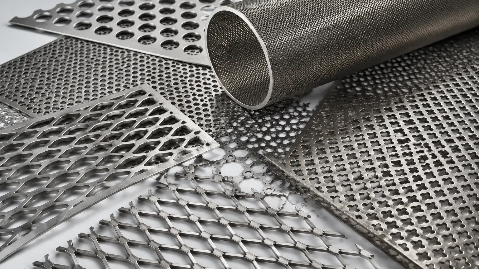
When an engineer reviews a perforated metal image, they are looking for specific geometric indicators that dictate flow dynamics and structural stability. In industrial filtration, the visual pattern—whether it is a staggered round hole, a straight square hole, or a complex hexagonal design—determines how a fluid or gas will interact with the medium.
A technical image or schematic provides the basis for calculating the "Open Area Percentage," which is the ratio of the area of the holes to the total area of the sheet. This percentage is the most vital metric for determining flow rate and pressure drop. A high open area typically allows for higher flow rates but may compromise the mechanical strength of the filter cartridge or support structure. Conversely, a lower open area provides greater rigidity but increases resistance to flow. Therefore, the visual confirmation of hole density and arrangement is the primary method for balancing these competing requirements during the initial design phase.
Differentiating Between Perforated and Expanded Metal Structures
While they are often grouped together, perforated and expanded metals are manufactured through distinct processes that result in different physical characteristics. Understanding these differences is crucial when analyzing a perforated metal image for a specific application.
Perforated Metal
Perforated metal is produced by punching a series of holes into a solid metal sheet. This process allows for extreme precision in hole size, shape, and spacing. Engineers often prefer perforated metal for high-precision filtration because the margins (the solid areas around the edges of the sheet) can be customized to facilitate welding or mounting into a housing. The holes can be as small as a few hundred microns or as large as several inches, depending on the thickness of the material and the intended use.
Expanded Metal
Expanded metal is created by simultaneously slitting and stretching a metal sheet. This process creates diamond-shaped openings and results in a three-dimensional structure. Unlike perforated metal, which is a flat 2D plane, expanded metal has "strands" and "bonds" that are set at an angle to the original plane of the sheet. This provides an inherent stiffness and a high strength-to-weight ratio. From a visual perspective, an expanded metal image will show a mesh-like appearance that is often used for secondary support in multi-layered filter elements or as a protective outer cage for delicate wire mesh filters.
Material Selection and Chemical Compatibility
An image cannot convey the chemical properties of the metal, which is why material selection must accompany any visual specification. In industrial filtration, stainless steel is the standard due to its corrosion resistance and durability.
* Stainless Steel 304: This is the most common grade used for general industrial applications. It offers excellent formability and is suitable for most water treatment and food processing environments where extreme chemical exposure is not a factor.
* Stainless Steel 316/316L: For more aggressive environments, such as chemical processing or marine applications, 316 stainless steel is preferred. The addition of molybdenum enhances resistance to pitting and crevice corrosion, particularly in chloride-rich environments.
* Specialty Alloys: In high-temperature or highly acidic environments, alloys like Monel, Inconel, or Hastelloy may be required.
When evaluating a perforated metal image, engineers must confirm that the material grade specified is compatible with the pH levels, temperatures, and chemical compositions of the process fluid. Failure to match the material to the environment can lead to premature failure through oxidation or stress corrosion cracking.
Calculating Open Area and Filtration Efficiency
The efficiency of a filter is directly tied to its geometric configuration. When viewing a perforated metal image, the arrangement of the holes—staggered versus straight—significantly impacts the open area calculation.
Staggered Patterns
A 60-degree staggered pattern is the most popular choice for industrial applications. It provides the highest open area for a given hole size and maintains uniform strength across the sheet. This pattern ensures that the fluid flow is distributed evenly, reducing localized high-velocity zones that could cause erosion or uneven cake buildup in filtration cycles.
Straight Patterns
Straight patterns, where holes are aligned in both horizontal and vertical rows, are generally less strong than staggered patterns. They are often chosen for aesthetic reasons or for very specific mechanical sorting applications where a linear path is required. However, in high-pressure hydraulic or chemical systems, straight patterns are less common due to their tendency to deform under heavy loads.
To calculate the open area of a round hole, 60-degree staggered pattern, the formula used is:
Open Area % = (D² x 90.69) / P²
*Where D is the hole diameter and P is the pitch (the distance from the center of one hole to the center of the adjacent hole).*
By analyzing the perforated metal image and confirming these dimensions, engineers can predict the pressure drop across the filter and ensure the system's pump or compressor is appropriately sized.
Manufacturing Precision and Quality Control Standards
A high-quality perforated metal image should represent a product free from manufacturing defects. In B2B procurement, the visual appearance of the sample or the technical drawing must be backed by rigorous quality control. Several factors must be verified:
1. Burr-Free Edges: The punching process can leave sharp burrs on the exit side of the hole. For filtration applications, these burrs must be removed through deburring or polishing to prevent them from breaking off and contaminating the downstream flow or damaging delicate filter membranes.
2. Flatness: Industrial sheets must remain flat to be properly integrated into filter housings. Internal stresses during the perforation process can cause the metal to curl or bow, requiring specialized leveling equipment to correct.
3. Hole Uniformity: Any variation in hole size across the sheet will lead to inconsistent filtration. Precision tooling and regular maintenance of the punching press are required to ensure that every hole matches the specification shown in the perforated metal image.
Maintenance and Longevity in Industrial Environments
The lifecycle of a perforated or expanded metal component depends heavily on its maintenance and the nature of the particles it is designed to capture. Unlike disposable synthetic filters, stainless steel perforated components are often designed to be cleaned and reused.
In applications like water treatment or large-scale chemical filtration, the perforated metal acts as a "strainer" or a support for finer wire mesh. Over time, particles can become lodged in the openings (blinding). The smooth surface of perforated metal makes it easier to clean via backwashing, ultrasonic cleaning, or chemical soaking compared to woven materials. When selecting a pattern from a perforated metal image, engineers should consider whether the hole geometry allows for easy release of captured solids during the cleaning cycle.
Procurement Checklist: From Image to Final Component
Before moving from the stage of reviewing a perforated metal image to placing an order, purchasing teams and engineers should confirm the following technical details to ensure the product is fit for purpose:
* Hole Shape and Size: Confirm the exact diameter (for round holes) or dimensions (for square/slotted holes).
* Pitch and Pattern: Specify whether the pattern is staggered (45 or 60 degrees) or straight.
* Material Grade: Ensure the alloy (e.g., SS304, SS316L) is certified and matches the application's chemical requirements.
* Sheet Thickness: Thicker materials provide more strength but may limit the minimum hole size achievable due to the "one-to-one" rule (hole diameter should generally not be smaller than the material thickness).
* Margins: Define the required solid areas on the edges for welding or bolting.
* Surface Finish: Determine if the part requires pickling, passivation, electropolishing, or simple deburring.
By focusing on these factual boundaries, industrial professionals can move beyond the visual appeal of a perforated metal image and secure components that offer the reliability and precision required for critical industrial processes. Whether the goal is to support a high-pressure hydraulic filter or to provide a durable screen for food processing, the transition from a visual concept to a high-performance metal component requires meticulous attention to engineering detail and manufacturing quality.
