


Strainer Drawing
In industrial fluid handling and process engineering, the transition from a conceptual system design to a functional physical installation relies heavily on technical documentation. Among the most critical documents for maintenance and procurement teams is the strainer drawing. A precise strainer drawing serves as the definitive blueprint that bridges the gap between engineering requirements and manufacturing reality, ensuring that the filtration component integrates seamlessly into the piping architecture while meeting specific performance parameters.
For engineers and purchasing managers, understanding how to interpret, verify, and utilize a strainer drawing is essential for minimizing downtime and avoiding costly installation errors. Whether dealing with Y-strainers, T-strainers, or complex Strainers & Baskets, the drawing provides the technical foundation for quality control and long-term operational reliability.
The Role of the Strainer Drawing in Industrial Engineering
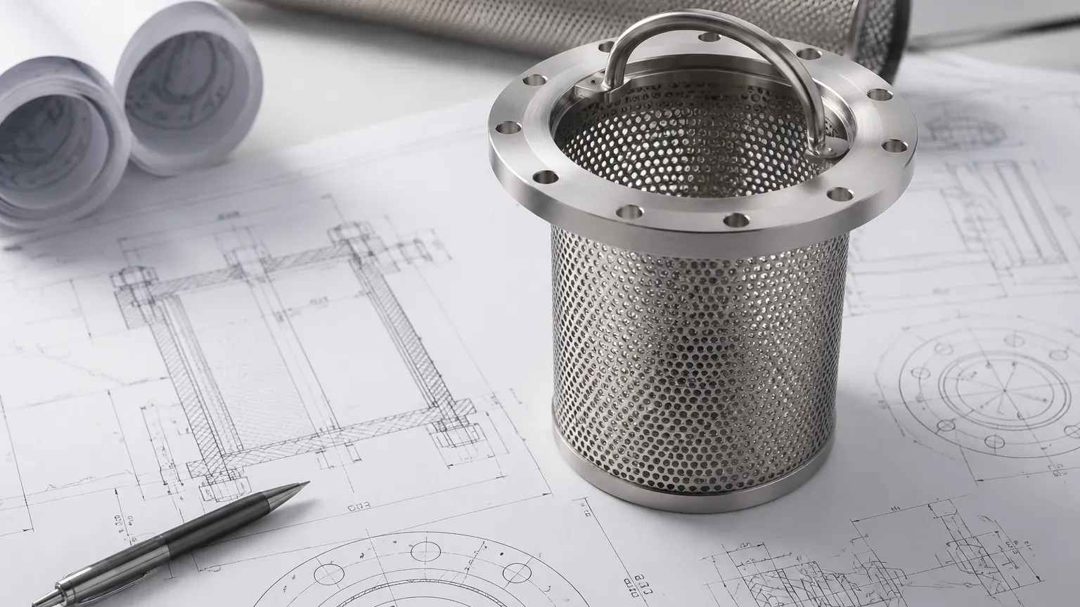
A strainer drawing is more than a simple visual representation; it is a legal and technical specification document. In B2B procurement, this document is used to confirm that the manufacturer’s output aligns with the facility’s mechanical requirements. It typically includes several specialized views, such as plan views, sectional elevations, and detailed blow-outs of the internal filtration media.
The primary purpose of the drawing is to define the physical boundaries of the unit. This includes the "face-to-face" dimensions, which are critical for ensuring the strainer fits between existing pipe flanges without requiring modification to the piping run. Furthermore, the drawing specifies the orientation of the blow-off port, the clearance required for basket removal, and the exact placement of pressure gauge tappings.
Key Components of a Technical Strainer Specification
When reviewing a strainer drawing, several key data points must be scrutinized to ensure the component will perform under the intended process conditions. These components generally fall into three categories: dimensional data, material specifications, and performance ratings.
Dimensional Accuracy and Clearance
Dimensional data is the most immediate concern during the installation phase. The drawing must clearly indicate the overall height, width, and connection sizes. One often overlooked detail in a strainer drawing is the "removal clearance." For basket-style strainers, the drawing must specify the vertical or horizontal space required to extract the internal basket for cleaning. If this clearance is not accounted for in the initial system layout, maintenance becomes impossible without dismantling the entire pipe section.
Material of Construction (MOC)
Industrial environments often involve corrosive chemicals, high temperatures, or stringent hygienic requirements. A professional drawing will include a detailed Bill of Materials (BOM) that specifies the grade of stainless steel (e.g., SUS 304, 316, or 316L) used for the housing, the mesh, and the support cage. It should also specify the gasket or O-ring material, such as EPDM, Viton, or PTFE, to ensure chemical compatibility with the process fluid.
Connection Standards
The drawing must define the connection type and standard. Whether it is an ANSI flange, a DIN standard, or an NPT thread, the drawing ensures that the strainer can be bolted or screwed into the system without the need for adapters that could introduce potential leak points.
Interpreting Filtration Media Details
The heart of any strainer is the internal element. In a technical strainer drawing, the specifications for the mesh or perforated plate are paramount. This section of the drawing defines the filtration accuracy and the structural integrity of the element.
Perforation and Mesh Size
The drawing should specify the hole diameter and the pitch (the distance between holes) for perforated metal backups. For finer filtration, it will detail the wire mesh count or the micron rating. Engineers use these figures to calculate the "Open Area Ratio," which is the ratio of the total area of the holes to the area of the inlet pipe. A high-quality design typically aims for an open area ratio of at least 6:1 to ensure low pressure drop and extended service intervals.
Structural Reinforcement
In high-pressure or high-viscosity applications, the filtration media is subject to significant mechanical stress. The strainer drawing must illustrate how the mesh is supported. This might include a heavy-gauge perforated metal basket that houses a finer mesh liner. The drawing should show the welding methods used—such as spot welding or continuous longitudinal seams—to ensure the basket does not collapse under a high differential pressure ($ΔP$).
Engineering Considerations for Custom Strainer Drawings
Standard off-the-shelf strainers often fail to meet the unique demands of specialized chemical processing or food production lines. In these instances, a custom strainer drawing becomes the primary tool for communication between the client and the OEM manufacturer.
Flow Dynamics and Pressure Drop
An optimized drawing takes into account the flow path of the fluid. Engineers look for designs that minimize turbulence and stagnant zones where solids might accumulate and cause localized corrosion. By reviewing the internal geometry shown in the drawing, engineers can estimate the initial pressure drop across the unit. If the drawing shows a restricted flow path, it may indicate that the strainer will require more frequent cleaning or a larger pump to maintain flow rates.
Custom Features and Accessories
Custom drawings allow for the inclusion of specialized features such as:
* Magnetic Inserts: For capturing fine ferrous particles that might pass through a standard mesh.
* Differential Pressure Taps: Pre-drilled and tapped holes for the installation of DP sensors, allowing for automated maintenance alerts.
* Heating Jackets: Essential for fluids that must be maintained at a specific temperature to prevent solidification, such as resins or chocolate.
Common Risks in Drawing Misinterpretation
Errors in the drafting or review process can lead to significant project delays. One of the most common risks is the failure to specify the "Effective Filtration Area." If a drawing only provides the gross surface area of the basket without accounting for the areas blocked by structural supports or welds, the actual performance will be lower than expected.
Another risk involves tolerance levels. In large-scale industrial piping, a discrepancy of even a few millimeters in the flange-to-flange dimension can prevent a strainer from being installed. A professional drawing should always include a tolerance table, specifying the allowable variance for every critical dimension. Furthermore, the drawing must clearly state the pressure and temperature ratings (e.g., ASME Class 150 or 300) to ensure the unit can safely withstand the maximum operating conditions of the facility.
Verification Checklist for Procurement Teams
Before approving a strainer drawing for production, procurement and engineering teams should conduct a final verification. This checklist ensures that the delivered product will meet all site requirements:
1. Connection Compatibility: Does the flange rating on the drawing match the existing piping?
2. Material Verification: Are the housing and internal materials suitable for the pH and temperature of the fluid?
3. Maintenance Access: Is there sufficient clearance shown in the drawing for basket removal or blow-down valve operation?
4. Filtration Accuracy: Does the mesh or perforation size align with the protection requirements of downstream equipment (e.g., pumps, nozzles, or heat exchangers)?
5. Seal Integrity: Is the gasket material specified and compatible with the process media?
The Manufacturer’s Role in Drawing Development
Working with a manufacturer that possesses deep technical expertise in stainless steel filtration allows for a more collaborative drawing process. A capable OEM provider does not simply follow a drawing; they analyze it for potential engineering improvements. For example, a manufacturer might suggest a change in the basket handle design to make it easier for operators to remove, or recommend a different welding technique to improve the longevity of the mesh in a high-vibration environment.
At Kaifil, the focus is on providing reliable, custom-engineered Strainers & Baskets that meet the exact specifications of demanding industrial applications. By utilizing advanced manufacturing capabilities, Kaifil ensures that every physical component matches the approved technical drawing with high precision. This commitment to accuracy helps global customers in the chemical, pharmaceutical, and water treatment sectors achieve efficient and cost-effective filtration performance.
Conclusion
The strainer drawing is the fundamental link between the engineering office and the factory floor. By providing a clear, detailed, and accurate representation of the required filtration component, it ensures that industrial systems operate safely and efficiently. For B2B professionals, investing the time to thoroughly review and refine these drawings is a vital step in the procurement process, leading to reduced maintenance costs, improved equipment protection, and a lower total cost of ownership.
