


Disc Filter Drawing
In the field of industrial filtration, the technical drawing serves as the primary communication bridge between engineering requirements and manufacturing reality. For precision components like Filter Discs & Packs, a detailed and accurate disc filter drawing is essential to ensure that the final product meets the rigorous demands of chemical processing, hydraulic systems, or food and beverage production. This article explores the critical elements of these drawings, the engineering considerations involved in their creation, and how technical specifications translate into filtration performance.
Understanding the Role of a Disc Filter Drawing in Industrial Procurement
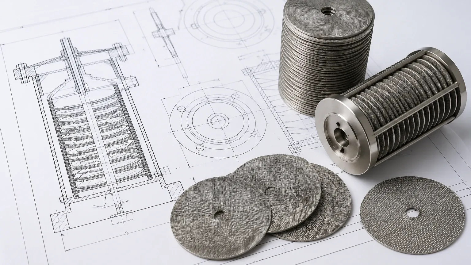
A technical drawing for a filter disc is more than just a visual representation; it is a comprehensive specification document that defines the physical and functional boundaries of the component. In B2B procurement, especially when dealing with custom stainless steel solutions, the drawing acts as the technical contract between the client and the manufacturer. It eliminates ambiguity regarding dimensions, material grades, and construction methods.
When an engineer provides a disc filter drawing, they are defining the parameters that will dictate the pressure drop, flow rate, and particle retention capabilities of the system. Without a precise drawing, there is a significant risk of manufacturing errors, such as incorrect mesh alignment in multi-layer packs or improper edge sealing, which can lead to bypass or structural failure under high-pressure conditions. For complex assemblies, the drawing must also account for how the disc interacts with the housing or the support plate, ensuring a leak-proof fit.
Critical Technical Specifications in Filter Disc Engineering
To create a functional Filter Discs & Packs specification, several technical variables must be explicitly detailed. These specifications are the foundation of the filtration process and determine the longevity of the component in a production environment.
Micron Rating and Mesh Count
One of the most common points of confusion in a disc filter drawing is the distinction between mesh count and micron rating. The mesh count refers to the number of openings per linear inch, while the micron rating defines the size of the particles the mesh is intended to retain. A professional drawing should specify both, along with the wire diameter, as these three factors together determine the open area percentage. The open area is a critical metric for calculating the initial pressure drop across the filter.
Weave Types
The method of weaving the stainless steel wire significantly impacts the disc's performance. Common weave types include:
- Plain Weave: The most standard configuration where wires cross over and under each other. It offers high flow rates but lower mechanical strength.
- Twill Weave: Allows for thicker wires and a heavier mesh, suitable for higher pressure applications.
- Dutch Weave: Provides a much finer filtration capability and superior strength by using different wire diameters for the warp and weft. This is often preferred for high-precision industrial applications.
Material Selection and Mesh Configuration in Drawing Standards
The choice of material is perhaps the most critical factor for durability. Most industrial filter discs are manufactured from stainless steel due to its corrosion resistance and thermal stability. However, specifying "stainless steel" is insufficient for a professional engineering drawing.
Alloy Grades
The disc filter drawing must specify the exact grade, such as AISI 304, 316, or 316L. In environments involving high chloride concentrations or acidic solutions, such as in chemical processing or marine applications, 316L is often required for its superior resistance to pitting and crevice corrosion. For extreme conditions, specialty alloys like 904L or Monel may be indicated. The drawing should also note any requirements for material certification (MTRs) to ensure traceability.
Multi-Layer vs. Single-Layer Packs
In many high-pressure or high-viscosity applications, such as polymer melt filtration, a single layer of mesh is insufficient. The drawing must then detail a "pack" configuration. This typically involves a fine filtration layer sandwiched between coarser support and drainage layers. The drawing should clearly show the sequence of these layers and the method of bonding them, whether through spot welding or a peripheral rim.
Common Geometric Configurations and Tolerances for Filter Discs & Packs
Geometry and tolerances are where the theoretical design meets the practicalities of the assembly line. A disc filter drawing must provide clear dimensional constraints to ensure compatibility with existing hardware.
Shape and Dimensions
While circular discs are the most common, industrial applications often require oval, rectangular, or ring-shaped filters. The drawing must specify the outer diameter (OD) and, if applicable, the inner diameter (ID). For multi-layer packs, the total thickness of the compressed stack is a vital measurement, especially if the disc must fit into a recessed seat with tight clearances.
Tolerance Standards
In precision engineering, a tolerance of +/- 0.1mm is often standard for the outer diameter of a filter disc. However, for specialized hydraulic or pharmaceutical applications, tighter tolerances may be required. The drawing should also specify the flatness of the disc. A warped or bowed disc can create gaps in the seal, leading to unfiltered fluid bypassing the media. Defining the "allowable out-of-flatness" ensures that the manufacturer uses the correct leveling and tensioning processes during production.
Edge Treatment
The perimeter of the disc is a frequent point of mechanical stress. A drawing should specify if the edges are to be left raw (cut), spot-welded, or encased in a metal rim (often made of aluminum, stainless steel, or copper). Rimmed edges provide structural integrity and a better sealing surface, which is crucial for preventing the fraying of wire mesh at the boundaries.
Identifying and Mitigating Risks in the Drawing-to-Production Pipeline
Transitioning from a disc filter drawing to a finished product involves several risks that can impact the total cost of ownership and system uptime. Understanding these risks allows engineers to address them during the design phase.
1. Mesh Displacement: In multi-layer packs, if the layers are not properly secured, they can shift during installation or operation. This changes the filtration characteristics. Specifying the number and location of spot welds on the drawing can mitigate this.
2. Thermal Expansion: In high-temperature processes, the filter disc and its housing may expand at different rates. If the drawing does not account for this thermal movement, the disc may buckle or the seal may fail. Engineers should specify the operating temperature range on the drawing so the manufacturer can recommend appropriate clearances.
3. Contamination Control: For pharmaceutical or food-grade applications, the drawing should include notes on cleaning standards, such as ultrasonic cleaning or passivation, to ensure the discs are free from manufacturing oils and metallic burrs.
Best Practices for Finalizing Custom Filtration Specifications
When preparing a disc filter drawing for a manufacturer like Kaifil, providing high-quality digital files is the first step toward a successful project. CAD formats such as DWG or DXF are preferred as they allow for direct integration into CNC cutting and laser welding systems.
Before finalizing the drawing, engineers should verify the following:
- Flow Direction: In asymmetrical or multi-stage packs, the direction of flow must be clearly marked. Installing a pack backward can lead to premature clogging or the collapse of the fine mesh layer.
- Effective Filtration Area (EFA): Ensure the drawing accounts for the area lost to rims or support structures. The EFA is what actually does the work, and overestimating it can lead to higher-than-expected flow velocities and reduced filter life.
- Sample Validation: For new designs, it is often prudent to request a prototype based on the drawing. This allows for physical fitment testing and bubble point testing to verify that the manufactured part matches the theoretical design.
By focusing on these technical details, purchasing teams and engineers can ensure that their Filter Discs & Packs are optimized for performance, durability, and cost-effectiveness. A well-executed drawing is the most effective tool for minimizing downtime and maintaining the integrity of industrial processes.
