


Liquid Gas Coalescer Filter
In industrial processing, the presence of liquid contaminants within gas streams poses a significant threat to equipment integrity and process efficiency. A liquid gas coalescer filter is a specialized component designed to remove sub-micron liquid aerosols and droplets from gas or air. Unlike standard particulate filters that simply trap solid debris, coalescing technology utilizes a multi-stage physical process to merge small droplets into larger ones, which then drain away by gravity.
For engineers and procurement teams, selecting the right coalescing solution requires a deep understanding of fluid dynamics, material compatibility, and structural design. As a manufacturer specializing in custom stainless steel filtration, Kaifil provides the precision-engineered components necessary to maintain high-performance gas separation in demanding environments. This guide explores the technical foundations, evaluation criteria, and engineering considerations for implementing liquid gas coalescer filters in industrial applications.
The Mechanics of Coalescence in Gas Streams
The primary function of a liquid gas coalescer filter is to separate a liquid phase (the dispersed phase) from a continuous gas phase. This is achieved through three primary mechanisms that occur within the filter media:
1. Direct Interception: Larger liquid droplets traveling in the gas stream collide with the fibers of the filter media. Because the droplets cannot follow the tortuous path of the gas through the media, they are captured on the fiber surface.
2. Inertial Impaction: As gas changes direction to move around the filter fibers, droplets with higher density and momentum continue in a straight path, impacting the fibers and adhering to them.
3. Brownian Diffusion: Extremely small droplets (typically less than 0.1 microns) exhibit random movement due to collisions with gas molecules. This erratic path increases the probability that they will come into contact with the filter media and become trapped.
Once these droplets are captured, they move along the fibers and collide with other droplets, merging into larger masses. This process continues until the droplets reach a size where gravity overcomes the aerodynamic drag of the gas stream, causing the liquid to fall to the bottom of the filter housing for collection and discharge.
Structural Design and Material Selection
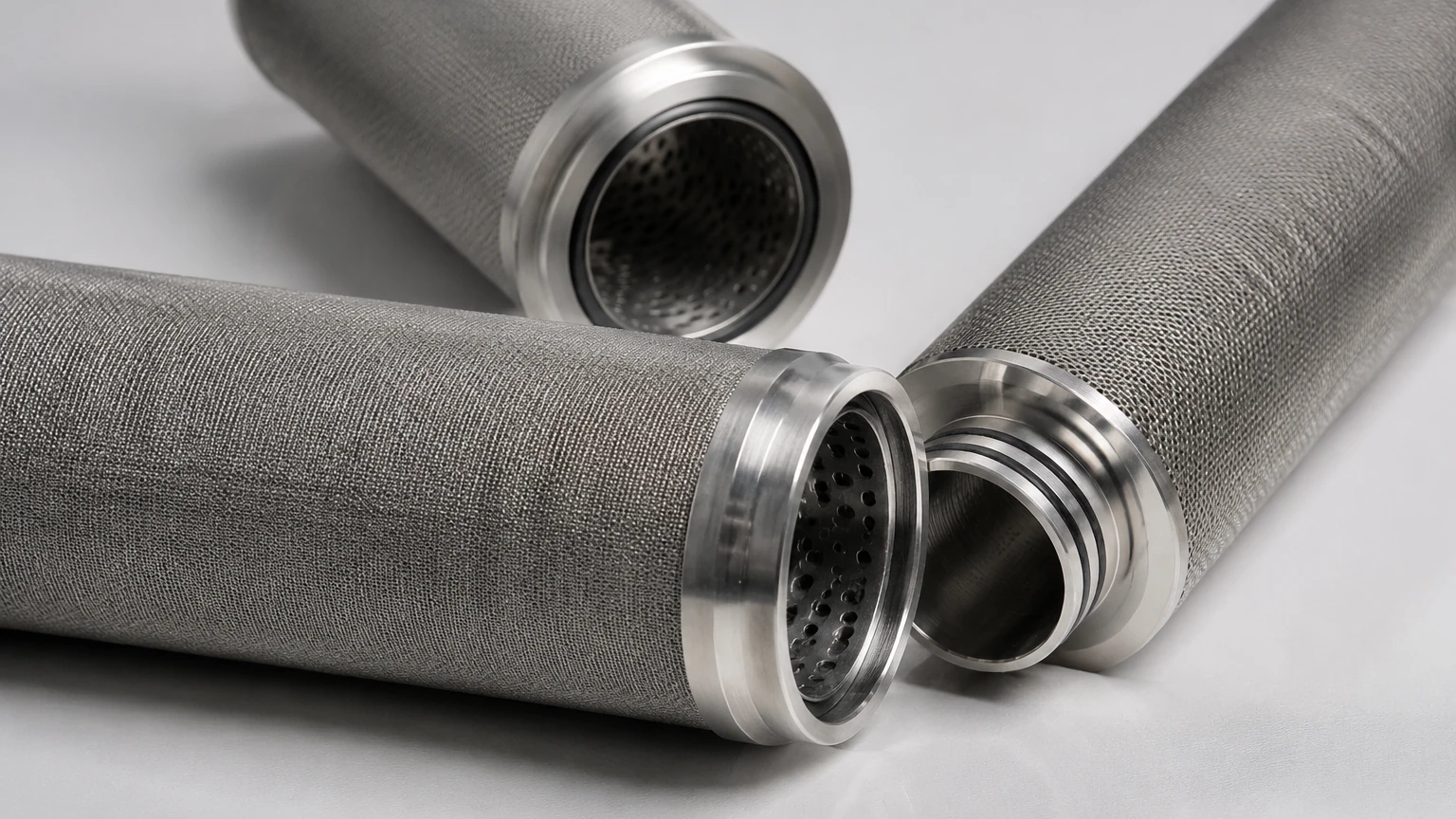
The effectiveness of a liquid gas coalescer filter is heavily dependent on its construction. For industrial applications involving corrosive gases, high temperatures, or high pressures, stainless steel is the preferred material for the filter’s structural components. At Kaifil, we focus on providing durable stainless steel filter cartridges and wire mesh components that serve as the backbone of these systems.
Media Layers
In a typical coalescing element, the media is arranged in layers. The inner layer is usually a high-efficiency borosilicate micro-glass or a specialized synthetic fiber designed for capture. Surrounding this is often a drainage layer—typically a coarse mesh or foam—that facilitates the downward movement of the coalesced liquid.
Support Cores
To withstand high differential pressures without collapsing, coalescer elements require robust inner and outer support cores. Stainless steel 304 or 316L perforated tubes or expanded metal are used to provide the necessary mechanical strength while maintaining maximum open area for gas flow.
End Caps and Seals
Proper sealing is critical to prevent gas bypassing. End caps, often made of stainless steel, are bonded to the media using high-temperature resins or mechanical seals. For aggressive chemical environments, the selection of O-ring materials (such as Viton, EPDM, or PTFE) must be carefully matched to the gas composition.
Key Evaluation Criteria for Engineers
When specifying a liquid gas coalescer filter, several performance metrics must be analyzed to ensure the system meets the required purity standards without excessive operational costs.
Filtration Efficiency and Micron Rating
Coalescers are often rated by their ability to remove droplets of a specific size, typically 0.3 microns. High-performance units can achieve efficiencies of 99.9% or higher. It is important to distinguish between "nominal" and "absolute" ratings; for critical downstream equipment protection, absolute ratings are generally required.
Saturated Pressure Drop
A coalescer filter will always have a higher pressure drop when it is wet (saturated) than when it is dry. Engineers must size the system based on the saturated pressure drop to ensure the compressor or gas source can maintain the required flow rate. A high pressure drop indicates either an undersized filter or a media that is becoming blinded by solid particulates.
Liquid Loading Capacity
This refers to the volume of liquid the filter can handle per unit of time. If the liquid loading exceeds the drainage rate of the coalescer, the element will become flooded, leading to "re-entrainment," where the gas stream picks up liquid from the saturated media and carries it downstream.
Common Risks and Operational Challenges
Even the most advanced liquid gas coalescer filter can fail if the operating conditions are not properly managed. Understanding these risks is essential for long-term reliability.
* Solid Particulate Contamination: Coalescing media is designed to capture liquids, but it is also very effective at trapping solids. If the gas stream contains high levels of dust, scale, or rust, the coalescer will plug rapidly. In such cases, a dedicated particulate pre-filter should be installed upstream.
* Chemical Incompatibility: Certain chemicals in the gas stream can degrade synthetic fibers or binders in the coalescing media. Utilizing stainless steel components for the housing and support structures mitigates structural failure, but the media itself must be verified against the gas chemistry.
* Flow Surges: Sudden increases in gas velocity can strip coalesced droplets from the drainage layer. Sizing the filter for peak flow rather than average flow is a critical engineering safeguard.
* Aerosol Concentration: If the concentration of liquid aerosols is too high, the coalescer may not be able to drain quickly enough. This often happens in natural gas applications where heavy hydrocarbon liquids are present.
Customization and OEM Solutions
No two industrial gas streams are identical. Factors such as gas density, viscosity of the liquid phase, and operating temperature vary significantly between a food-grade CO2 system and a high-pressure natural gas pipeline. Consequently, off-the-shelf solutions often fall short of performance expectations.
Customization allows for the optimization of the filter’s surface area and media density. For example, a pleated design can significantly increase the available surface area, reducing the face velocity of the gas and improving the chances for coalescence. Kaifil works closely with technical teams to develop OEM filtration components that fit specific housing geometries and performance targets. Whether you are designing a new system or looking to improve the service life of an existing installation, reviewing technical specifications and material options is the first step toward optimization. You can Main Page to explore our manufacturing capabilities and engineering support for custom metal filtration solutions.
Maintenance and Replacement Cycles
Monitoring the health of a liquid gas coalescer filter is primarily done through differential pressure (ΔP) measurement.
1. Initial ΔP: The pressure drop across a new, dry element.
2. Stabilized ΔP: The pressure drop once the element has reached a state of equilibrium (fully saturated and draining).
3. Terminal ΔP: The point at which the filter must be replaced. For most industrial systems, this is between 10 and 15 psi (0.7 to 1.0 bar).
Operating beyond the terminal ΔP not only increases energy costs for the compressor but also risks media rupture or bypass. Regular inspection of the drainage system (auto-drains or manual valves) is also necessary to ensure that the removed liquid is actually leaving the filter housing and not backing up into the element.
Conclusion: Selecting the Right Partner
A liquid gas coalescer filter is a critical line of defense for turbines, compressors, and sensitive analytical instruments. By focusing on high-quality materials like stainless steel and ensuring the design accounts for the specific nuances of the gas stream, engineers can significantly reduce downtime and maintenance costs.
When selecting a supplier, prioritize those who understand the technical requirements of industrial separation. A manufacturer should be able to provide detailed information on material grades, pressure ratings, and customization options. For professionals seeking reliable, custom-manufactured filtration components, Kaifil offers the expertise needed to navigate complex filtration challenges and deliver durable, high-efficiency solutions tailored to specific industrial needs.
