


Continuous Automatic Filter
In modern industrial processing, the transition from batch operations to continuous flow systems has necessitated a shift in filtration technology. A continuous automatic filter is a critical component in systems where downtime for manual cleaning is either economically unfeasible or technically restrictive. These systems are designed to remove suspended solids from liquid streams while maintaining a constant flow, utilizing self-cleaning mechanisms that trigger based on time intervals or differential pressure changes. For engineers and procurement teams, understanding the mechanical nuances, material requirements, and integration parameters of these filters is essential for optimizing plant efficiency and protecting downstream equipment.
Industrial filtration is no longer just about particle removal; it is about process stability. Whether in chemical processing, water treatment, or the food and beverage industry, the reliability of a continuous automatic filter depends heavily on the quality of its internal components, particularly the stainless steel filter elements that withstand the rigors of automated cleaning cycles.
The Mechanics of Continuous Automatic Filtration
The primary advantage of a continuous automatic filter is its ability to operate without human intervention. The system typically monitors the differential pressure (ΔP) between the inlet and the outlet. As contaminants accumulate on the surface of the filter element, the resistance to flow increases, causing the ΔP to rise. Once a pre-set threshold is reached, the automatic cleaning cycle is initiated.
There are two dominant mechanical approaches to self-cleaning in these systems:
1. Backwashing (Reverse Flow): This method uses a portion of the filtered fluid (or an external clean fluid/gas source) to flow in the reverse direction through the filter media. This high-velocity reverse flow dislodges the accumulated debris from the surface of the mesh, which is then flushed out through a dedicated drain or purge valve. This is highly effective for removing particulate from woven wire mesh or wedge wire elements.
2. Mechanical Scraping: In applications involving high-viscosity fluids or sticky contaminants, a mechanical scraper or brush travels across the surface of the filter element. This physical action shears the "filter cake" from the media, allowing it to settle in a collection chamber at the bottom of the housing for periodic removal. This method is often preferred when fluid loss must be minimized.
Both methods rely on the structural integrity of the filter element. Unlike disposable cartridges, the elements used in a continuous automatic filter must be engineered to survive thousands of cleaning cycles without deformation or loss of filtration accuracy.
Material Engineering and Filter Element Design
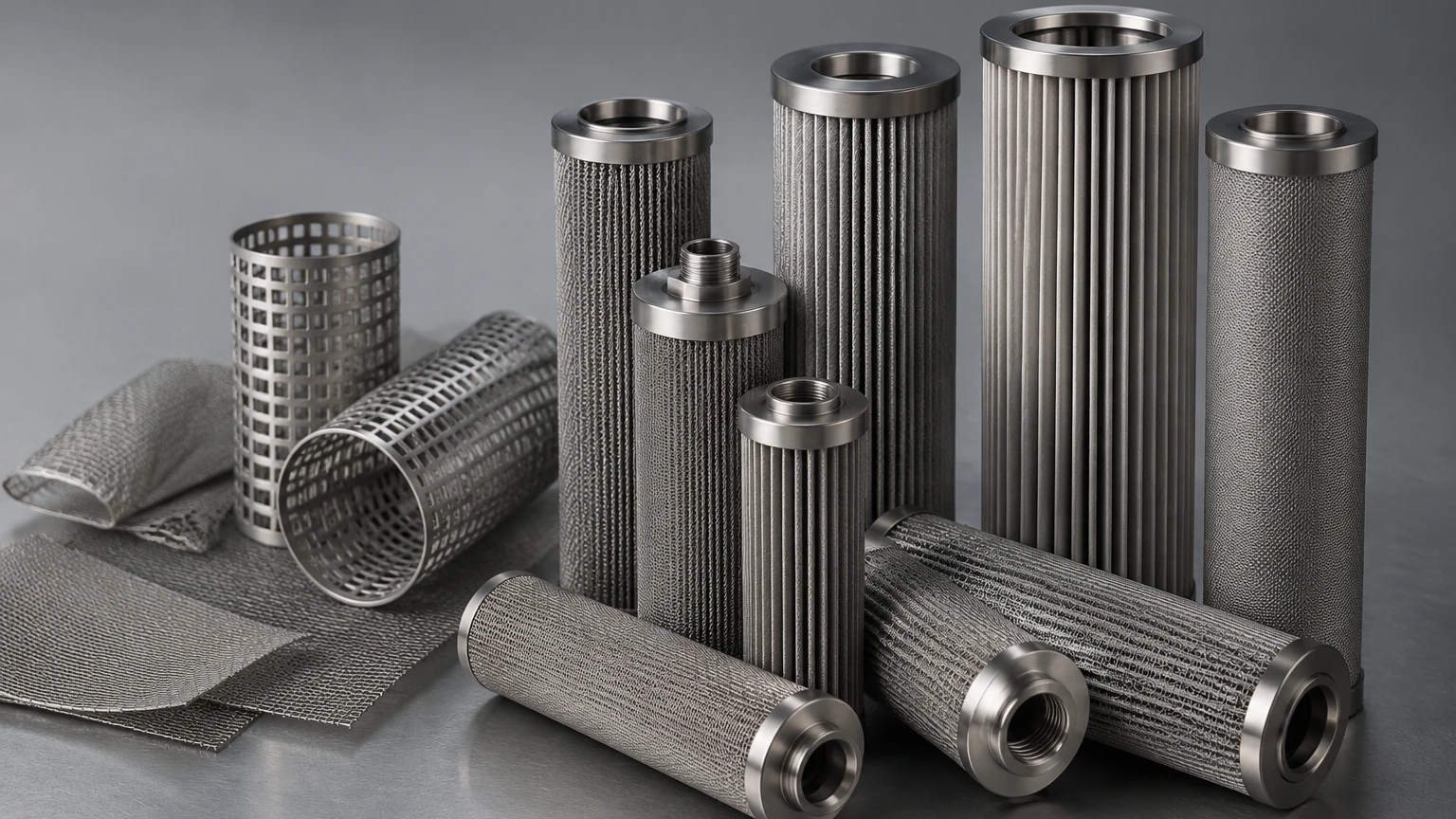
The heart of any continuous automatic filter is the filter element. Because these systems are designed for longevity, the selection of materials is usually restricted to high-grade alloys. Stainless steel 304 and 316L are the industry standards due to their corrosion resistance and mechanical strength.
Wedge Wire Elements
Precision-engineered wedge wire is often the preferred choice for automatic scraping filters. The V-shaped profile of the wire provides a "point contact" for particles, which significantly reduces the risk of blinding or clogging. The widening gap between the wires allows particles that pass the initial surface to flow through freely, making the backwashing process more efficient.
Sintered and Woven Wire Mesh
For finer filtration requirements, multi-layer sintered wire mesh provides a combination of high permeability and structural rigidity. By sintering multiple layers of stainless steel mesh together, manufacturers can create a media that offers the precision of fine weaving with the mechanical support required to withstand high-pressure backwash pulses. Engineers often look to the Main Page of specialist manufacturers to evaluate the different configurations of mesh and wedge wire available for their specific housing designs.
Critical Performance Parameters for Engineers
When specifying a continuous automatic filter, several technical variables must be analyzed to ensure the system meets the application's demands. A mismatch in any of these areas can lead to premature element failure or insufficient filtration.
* Micron Rating and Efficiency: It is vital to distinguish between nominal and absolute micron ratings. In continuous systems, the buildup of a "filter cake" can actually improve filtration efficiency over time, but the initial mesh size must be precisely matched to the smallest particle that could damage downstream components.
* Flow Rate and Flux: The flux (flow rate per unit of filter area) determines the velocity at which the fluid passes through the media. High flux rates can drive particles deeper into the mesh, making them harder to remove during the cleaning cycle. Designing for a lower flux often results in longer element life and more effective cleaning.
* Viscosity and Temperature: The viscosity of the fluid directly impacts the differential pressure. High-viscosity liquids require more robust mechanical scrapers and potentially larger surface areas to maintain the required flow rates without triggering constant cleaning cycles. Similarly, temperature fluctuations can affect material expansion, necessitating careful tolerances in the scraper-to-element interface.
Industry-Specific Integration Challenges
Different industries impose unique constraints on the design of a continuous automatic filter. For example, in the Food and Beverage sector, the filter must comply with hygienic standards. This means the internal components must have a low surface roughness (Ra) to prevent bacterial growth and must be capable of withstanding Clean-in-Place (CIP) chemicals.
In Chemical Processing, the primary concern is chemical compatibility. While 316L stainless steel is versatile, highly corrosive environments may require specialized alloys like Duplex stainless steel or Hastelloy. The seals and gaskets within the automatic valve assembly must also be resistant to the process fluid to prevent leaks during the purge cycle.
In Water Treatment and Cooling Systems, the challenge is often the sheer volume of debris. Continuous automatic filters in these applications must handle high solids loading without excessive fluid loss during backwashing. The design of the purge valve and the duration of the backwash cycle are critical to maintaining the water balance of the overall system.
Evaluating the Total Cost of Ownership (TCO)
While the initial capital expenditure (CAPEX) for a continuous automatic filter is significantly higher than that of a manual bag or cartridge filter housing, the Total Cost of Ownership is often much lower in industrial settings. The primary cost drivers in filtration are:
1. Labor Costs: Manual filters require operators to stop the process, open the housing, replace the media, and restart the system. In a continuous system, labor is reduced to periodic inspections and occasional seal replacements.
2. Consumable Costs: Continuous systems utilize permanent stainless steel elements. Instead of purchasing, storing, and disposing of thousands of filter bags or cartridges annually, a plant makes a one-time investment in a high-quality metal element.
3. Product Loss: Every time a manual filter is opened, process fluid is lost. Furthermore, the backwash cycles in modern automatic filters are optimized to use the minimum amount of fluid necessary, often less than 1% of the total throughput.
4. Energy Consumption: By maintaining a lower average differential pressure through frequent, automated cleaning, the system reduces the load on feed pumps, leading to measurable energy savings over the life of the equipment.
Customization and OEM Integration
Many industrial equipment manufacturers (OEMs) integrate a continuous automatic filter into their larger skids, such as hydraulic power units or fuel oil modules. In these cases, the standard "off-the-shelf" filter may not fit the spatial or performance requirements. Customization becomes necessary, involving the design of bespoke filter elements that fit specific housing geometries while maintaining the required filtration area.
Working with a manufacturer that understands the nuances of stainless steel fabrication allows for the development of elements with reinforced end caps, specialized support cores, and custom mesh layers. This level of customization ensures that the filter element is not the weak link in an otherwise robust automated system.
Conclusion: Selecting the Right Filtration Partner
The implementation of a continuous automatic filter is a strategic decision to prioritize process uptime and operational efficiency. However, the success of the system is fundamentally tied to the quality of the filtration media. Engineers must confirm that their suppliers use verified materials, employ advanced welding and sintering techniques, and can provide the technical documentation necessary for industrial compliance.
By focusing on the engineering details—from the micron rating and material grade to the mechanical stresses of the cleaning cycle—purchasing teams can ensure they are investing in a solution that provides long-term reliability. For those seeking to optimize their filtration processes, reviewing the technical capabilities and product ranges on a manufacturer's Main Page is the first step toward achieving high-performance, automated liquid-solid separation.
