


Hydrocyclone Separators
In industrial process engineering, the efficient separation of solids from liquids is a fundamental requirement for protecting downstream equipment, ensuring product purity, and managing waste streams. Hydrocyclone separators represent a critical category of static separation technology. Unlike mechanical filters that rely on physical barriers, hydrocyclones utilize centrifugal force generated by fluid pressure to achieve separation based on particle density and size.
For engineers and procurement teams, understanding the technical nuances of hydrocyclone separators is essential for optimizing system performance. These devices are often the first line of defense in a multi-stage filtration circuit, removing the bulk of heavy or coarse solids before the fluid reaches precision components such as stainless steel wire mesh filters or sintered metal cartridges. This guide examines the engineering principles, design variables, and operational considerations necessary for the successful implementation of hydrocyclone technology.
Principles of Centrifugal Separation
The operation of hydrocyclone separators is governed by fluid dynamics and the application of Newton’s laws of motion. The process begins when a pressurized slurry or liquid enters the cylindrical section of the hydrocyclone through a tangential inlet. This tangential entry transforms the linear velocity of the fluid into a high-velocity circular motion, creating a primary vortex that moves downward toward the conical section.
As the fluid rotates, centrifugal forces push the heavier and coarser particles toward the outer wall of the cyclone. These particles move downward along the wall and are eventually discharged through the bottom opening, known as the apex or underflow. Simultaneously, a secondary, upward-moving inner vortex forms in the center of the unit. This inner vortex carries the lighter fluid and finer particles upward through the vortex finder and out of the top discharge, known as the overflow.
The efficiency of this separation is highly dependent on the balance between centrifugal force (which drives particles toward the wall) and drag force (which pulls particles toward the center vortex). For engineers, the goal is to calibrate the pressure and flow rate to ensure that the target particle size—the "cut point"—is effectively directed to the underflow.
Key Design Components and Geometry
The performance of hydrocyclone separators is dictated by their internal geometry. Each component plays a specific role in defining the separation efficiency and the pressure drop across the system:
1. The Inlet: The size and shape of the inlet determine the entry velocity and the initial flow pattern. A rectangular or involute inlet design is often preferred to reduce turbulence and minimize wear near the entry point.
2. The Cylindrical Section: This section provides the residence time necessary for the primary vortex to stabilize. The diameter of this section is the primary factor in determining the unit's capacity and the centrifugal force generated.
3. The Vortex Finder: This tube extends into the cylindrical section from the top. It prevents the short-circuiting of the feed directly into the overflow and helps stabilize the inner vortex. Its length and diameter are critical for controlling the cut point.
4. The Conical Section: The angle of the cone influences the acceleration of the fluid and the concentration of the solids. Steeper angles generally provide finer separation but may increase the risk of plugging.
5. The Apex (Underflow Orifice): This is the narrowest part of the hydrocyclone. The diameter of the apex controls the volume of the underflow and the concentration of the discharged solids. If the apex is too small, a phenomenon known as "roping" occurs, where solids accumulate and block the air core, severely degrading separation efficiency.
Engineering Evaluation: Efficiency and Pressure Drop
When selecting hydrocyclone separators, engineers primarily focus on the cut point ($d_{50}$) and the pressure drop ($ΔP$). The $d_{50}$ represents the particle size at which 50% of the mass reports to the underflow and 50% to the overflow.
Several factors influence these metrics:
* Centrifugal Force: Higher pressure at the inlet increases the velocity and the resulting centrifugal force, leading to a finer cut point. However, this also increases the pressure drop, which requires more pumping energy.
* Fluid Viscosity: Increased viscosity increases the drag force on particles, making it harder for them to reach the outer wall. This results in a coarser cut point.
* Solid Concentration: High concentrations of solids can lead to particle-particle interference (hindered settling), which reduces separation efficiency. Hydrocyclones are typically most effective at solid concentrations below 10-15% by volume.
* Diameter Relationship: Generally, smaller diameter hydrocyclones generate higher centrifugal forces and achieve finer separations than larger units. In high-capacity applications requiring fine separation, engineers often use a "manifolded" approach, where multiple small hydrocyclones operate in parallel.
Material Considerations for Industrial Longevity
Because hydrocyclone separators operate at high velocities and often handle abrasive slurries, material selection is paramount for reducing the total cost of ownership. The internal surfaces are subject to constant impingement and sliding abrasion.
In many industrial applications, stainless steel is the preferred material for the outer shell due to its structural integrity and corrosion resistance. For the internal wear surfaces, manufacturers often utilize replaceable liners made from materials such as:
* High-Alumina Ceramics: Excellent for extreme abrasion but brittle and sensitive to thermal shock.
* Polyurethane or Natural Rubber: Effective for fine, abrasive particles and provides good impact resistance.
* Hardened Alloys: Used in high-temperature or high-pressure environments where polymers may fail.
For specialized chemical processing or pharmaceutical applications, the entire unit may be fabricated from high-grade stainless steel with precision-polished internal surfaces to prevent contamination and facilitate Cleaning-in-Place (CIP) protocols.
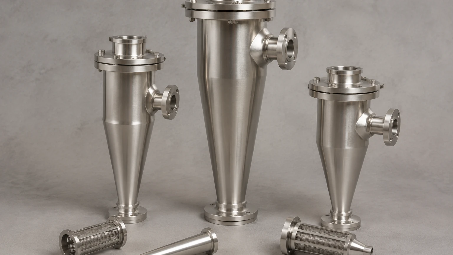
Integrating Hydrocyclones with Precision Filtration
Hydrocyclone separators are rarely used in isolation. In a sophisticated filtration system, they serve as a pre-treatment stage to remove the bulk of heavy solids. This protects secondary filtration stages—such as those found on our Main Page—from premature loading and mechanical damage.
By removing 90% or more of the coarse solids, a hydrocyclone significantly extends the service life of stainless steel filter cartridges or wire mesh screens. This synergy reduces the frequency of backwashing or manual cleaning cycles for the fine filters, leading to lower operational costs and more consistent downstream fluid quality. When designing a system, engineers must ensure that the flow rate and pressure supplied to the hydrocyclone are compatible with the requirements of the subsequent filtration equipment.
Common Operational Risks and Troubleshooting
Despite having no moving parts, hydrocyclone separators require careful monitoring to maintain peak performance. Common issues include:
* Roping: As mentioned, this occurs when the underflow solids concentration is too high, causing the discharge to look like a solid rope rather than a fan-like spray. This indicates that the apex is undersized or the solids load has exceeded the design capacity.
* Plugging: Large debris or tramp material can lodge in the apex or the inlet, disrupting the vortex and causing all material to bypass to the overflow. Installing a coarse strainer upstream can mitigate this risk.
* Air Core Instability: A stable air core is essential for the formation of the inner vortex. If the discharge is restricted or if there is excessive air entrainment in the feed, the air core may collapse, leading to poor separation.
* Erosion: Regular inspection of the apex and the lower conical section is necessary. Even small changes in the internal geometry due to wear can significantly shift the cut point and reduce efficiency.
Technical Checklist for Procurement
To ensure the correct specification of a hydrocyclone separator, the following data should be confirmed before proceeding with a purchase or custom design:
1. Particle Size Distribution (PSD): A full analysis of the solids in the feed is necessary to determine the required cut point.
2. Specific Gravity: The density of both the liquid and the solid particles must be known, as separation is driven by the density differential.
3. Flow Rate (Minimum, Normal, Maximum): Hydrocyclones are flow-sensitive; operating outside the design flow range will result in poor separation.
4. Chemical Compatibility: Confirm that the housing and liner materials are compatible with the process fluid, especially in high-temperature or acidic environments.
5. Downstream Requirements: Define the maximum allowable particle size for the subsequent filtration stages to ensure the hydrocyclone is correctly integrated into the overall process.
By following these engineering guidelines, facilities can implement hydrocyclone separators that provide reliable, low-maintenance solids separation, ultimately enhancing the efficiency and longevity of the entire industrial filtration circuit.
