


Disc Filter Symbol
In the world of industrial engineering and fluid power systems, clear communication through standardized schematics is essential for safety, maintenance, and system optimization. One of the most fundamental yet critical components found in these diagrams is the disc filter. Whether appearing in a complex Piping and Instrumentation Diagram (P&ID) or a high-pressure hydraulic circuit, the disc filter symbol serves as a technical shorthand that informs engineers about the presence, location, and function of filtration media within a system.
Understanding the nuances of these symbols—and the physical Filter Discs & Packs they represent—is vital for procurement officers, system designers, and maintenance technicians. This guide explores the technical standards of filter symbols, the engineering characteristics of disc filters, and how to translate a schematic requirement into a high-performance filtration solution.
1. Understanding the Disc Filter Symbol in Engineering Schematics
Engineering symbols are governed by international standards such as ISO 1219 for fluid power systems and ANSI/ISA-5.1 for instrumentation. When an engineer looks at a schematic, the disc filter symbol provides immediate information about the flow direction and the filtration intent.
Standard Filter Representations
In most hydraulic and pneumatic schematics, a filter is represented by a diamond shape (a square rotated 45 degrees) with a dashed line across the center, perpendicular to the flow. This dashed line represents the filter element itself.
For specific disc-style filtration, the symbol may be modified or accompanied by technical notes. In P&IDs, a filter might be shown as two parallel lines with a diagonal line between them, or as a simple circle with a line through it, depending on the specific industry standard being used. The primary goal of the symbol is to indicate a point where solid contaminants are separated from the liquid or gas stream.
Distinguishing Between Filters and Strainers
It is common to confuse the symbol for a filter with that of a strainer. In many standards, a strainer is represented by a diamond with a single diagonal line, whereas a filter uses a dashed line to indicate a finer degree of separation. For applications requiring Filter Discs & Packs, the distinction is critical: filters are generally designed to remove smaller particles (microns) compared to the larger debris captured by strainers.
2. Technical Specifications of Filter Discs & Packs
While the disc filter symbol on a drawing indicates where a filter is needed, it does not specify the material or construction required for the application. Engineers must define several technical parameters to ensure the physical component matches the schematic’s intent.
Material Selection
Stainless steel is the industry standard for disc filters due to its durability and resistance to extreme environments. Common grades include:
* SS 304: Suitable for general industrial applications with moderate corrosion risks.
* SS 316/316L: Preferred for chemical processing, pharmaceutical, and marine environments due to superior resistance to pitting and chlorides.
* Specialty Alloys: For high-temperature or highly corrosive environments, alloys like Monel, Inconel, or Hastelloy may be specified.
Mesh Types and Weave Patterns
The filtration performance is determined by the weave of the wire mesh.
* Plain Weave: The most common type, where wires cross over and under each other. It offers high flow rates but lower mechanical strength.
* Dutch Weave: Uses thicker warp wires and thinner, closely packed weft wires. This creates a dense, strong mesh capable of very fine filtration (down to 5-10 microns).
* Twilled Weave: Allows for thicker wires in a given mesh count, providing increased strength for high-pressure applications.
3. Engineering Considerations for Selection
When translating a disc filter symbol from a drawing into a purchase order, several engineering factors must be evaluated to prevent system failure or inefficiency.
Pressure Drop ($ΔP$)
Every filter introduces a restriction to the flow. The pressure drop across Filter Discs & Packs must be calculated based on the fluid viscosity, flow velocity, and the open area of the mesh. An incorrectly specified disc can lead to excessive backpressure, which may damage pumps or reduce system throughput.
Mechanical Strength and Layering
In high-pressure systems, a single layer of wire mesh may deform or burst. To solve this, engineers specify multi-layer filter packs. These packs often consist of:
1. Filtration Layer: The fine mesh that determines the micron rating.
2. Support Layers: Coarser mesh layers on either side of the filtration layer that provide structural integrity and prevent the fine mesh from collapsing under pressure.
3. Drainage Layers: Layers that help distribute the fluid evenly across the filtration surface.
Edge Treatment and Framing
To ensure a proper seal within the housing and to prevent fraying, disc filters often require specific edge treatments. Options include:
* Spot Welding: Multiple layers are welded together at the edges.
* Aluminum or Copper Rim: The edges are enclosed in a metal frame, which acts as a gasket and provides a rigid mounting surface.
* Unrimmed: Raw cut edges, typically used when the disc is held in place by a mechanical clamp or within a precision-machined recess.
4. Applications in Industrial Environments
The presence of a disc filter symbol is common across a wide range of industries, each with unique performance requirements.
Plastic and Rubber Extrusion
In polymer melt filtration, filter discs (often called screen packs) are used to remove unmelted resins and contaminants from the molten plastic. These discs must withstand extremely high temperatures and pressures. The use of multi-layer packs is standard here to ensure the mesh does not tear during the extrusion process.
Chemical and Petrochemical Processing
Disc filters are used in catalyst recovery and the removal of impurities from corrosive chemical streams. The ability of stainless steel to maintain its properties at high temperatures makes it the ideal choice for these volatile environments.
Hydraulic and Lubrication Systems
In hydraulic circuits, the disc filter symbol often appears before sensitive components like servo valves or actuators. These components have very tight tolerances, and even microscopic particles can cause catastrophic failure. Precision-engineered Filter Discs & Packs provide the necessary protection without significantly impacting the response time of the hydraulic system.
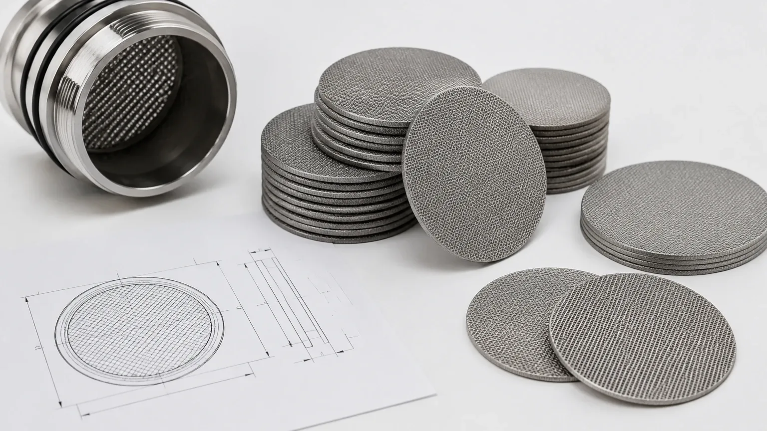
5. Customization and OEM Capabilities
Standardized symbols represent a function, but industrial applications often require bespoke physical designs. Kaifil specializes in translating technical drawings and schematic requirements into custom filtration components.
Geometry and Sizing
While "disc" implies a circular shape, industrial filters can be manufactured in various geometries, including oval, rectangular, or ring-shaped (donut) designs. Precision laser cutting or die-stamping ensures that the final product fits perfectly into the intended housing, maintaining the seal integrity required by the system design.
Prototyping for Performance
For new system designs, engineers may require prototypes to test flow characteristics and filtration efficiency. Working with a manufacturer that understands the technical implications of the disc filter symbol allows for iterative design improvements before moving to mass production. This includes adjusting mesh counts, layering sequences, and frame materials to optimize the total cost of ownership.
6. Maintenance and Replacement Cycles
A schematic symbol remains static, but the physical filter is a consumable or a component requiring periodic cleaning. Understanding the lifecycle of Filter Discs & Packs is essential for operational continuity.
Monitoring Contamination
In many systems, the disc filter symbol is accompanied by a differential pressure gauge symbol. When the pressure drop across the filter exceeds a predetermined threshold, it indicates that the mesh is loaded with contaminants. At this point, the filter must be cleaned or replaced.
Cleaning vs. Disposal
Stainless steel disc filters offer the advantage of being cleanable. Techniques such as ultrasonic cleaning, backflushing, or chemical cleaning can restore the filter's performance. However, in applications involving hazardous chemicals or where the mesh has suffered mechanical fatigue, replacement is the safer and more cost-effective option. Engineers should establish clear protocols for when a disc has reached its end-of-life based on the number of cleaning cycles and the integrity of the wire weave.
7. Conclusion: From Schematic to Solution
The disc filter symbol is more than just a mark on a blueprint; it is a critical instruction that defines the protection of an entire industrial process. By understanding the standards that govern these symbols and the technical complexities of the Filter Discs & Packs they represent, engineers can make more informed decisions regarding material selection, construction, and maintenance.
Selecting the right filtration component requires a balance of micron precision, mechanical strength, and chemical compatibility. Whether you are designing a new hydraulic system or optimizing a chemical processing line, partnering with a manufacturer that possesses deep technical expertise in stainless steel filtration ensures that the physical reality of your system matches the precision of your engineering drawings. For reliable, high-performance filtration that meets the most demanding industrial specifications, focus on the details that the symbol represents: the quality of the wire, the precision of the weave, and the durability of the final assembly.
