


Well Filter Pack Design
In industrial water abstraction, chemical processing, and oil and gas extraction, the integrity of a well is fundamentally dependent on its completion strategy. Well filter pack design serves as the critical interface between the geological formation and the mechanical extraction system. A poorly designed filter pack leads to sand production, equipment erosion, and premature well failure, while an optimized design ensures high hydraulic efficiency and long-term operational stability.
For engineers and procurement teams, understanding the technical nuances of well filter pack design is essential for selecting the right mechanical components, such as Filter Discs & Packs, and ensuring that the physical media matches the specific requirements of the borehole environment. This article examines the engineering principles, material considerations, and selection methodologies required for effective well filtration.
The Fundamental Role of the Filter Pack
The primary objective of well filter pack design is to create a permeable envelope around the well screen that prevents the migration of fine formation particles into the wellbore while allowing the target fluid to flow with minimal resistance. This process is often referred to as sand control.
In many industrial applications, the "filter pack" consists of two distinct but integrated elements: the primary filter media (often high-purity silica sand or glass beads) and the mechanical retention system (the well screen or specialized filter assemblies). The mechanical system must be engineered to retain the filter media, while the filter media is sized to retain the formation solids. If the mechanical component, such as a series of multi-layer mesh packs, is not precisely matched to the media size, the entire system will fail through either plugging or catastrophic sand bypass.
Engineering Principles of Well Filter Pack Design
Designing an effective filter pack requires a quantitative analysis of the formation. The process begins with a sieve analysis of the formation samples to determine the grain size distribution.
Sieve Analysis and Grain Size Distribution
Engineers plot the results of a sieve analysis on a semi-logarithmic graph to produce a grain-size distribution curve. From this curve, specific values are identified:
- d10: The size of the sieve opening through which 10% of the sample passes.
- d50: The median grain size (50% passing).
- d60: The size through which 60% of the sample passes.
The Uniformity Coefficient (Cu), defined as d60/d10, indicates how well-sorted the formation is. A Cu of less than 2.5 suggests a very uniform formation, whereas a Cu greater than 5 indicates a non-uniform, widely graded formation. Well filter pack design must account for these variations; non-uniform formations often require more complex, multi-layered filtration strategies to prevent "fines migration."
The Pack-to-Formation Ratio
The most widely accepted standard for sizing the filter pack is the pack-to-formation ratio (P/F ratio). Based on the work of Terzaghi and later refined by Schwartz, the general rule is that the d50 of the filter pack should be between 4 to 6 times the d50 of the formation sand. If the ratio is too low (less than 4), the pack may be too restrictive, causing excessive pressure drops. If the ratio is too high (greater than 9), the formation sand will move through the pack, leading to well sanding.
Mechanical Components: Filter Discs & Packs in Well Systems
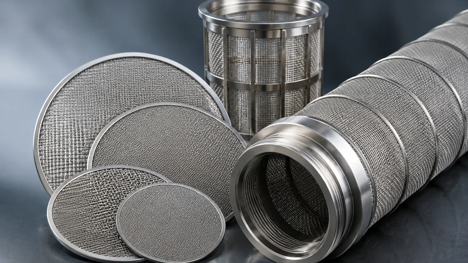
While the gravel or sand pack acts as the depth filter, the mechanical screen or disc assembly provides the final barrier and structural support. In high-pressure or high-temperature (HPHT) environments, or in specialized chemical injection wells, traditional wire-wrapped screens may be supplemented or replaced by precision-engineered Filter Discs & Packs.
These components are typically constructed from multiple layers of stainless steel wire mesh, sintered together to create a rigid, porous structure. In well filter pack design, these discs serve several functions:
1. Secondary Sand Retention: In the event of a partial failure of the gravel pack, the precision mesh layers provide a secondary defense.
2. Flow Distribution: They help equalize the flow velocity across the intake area, reducing the risk of localized "hot spots" where high-velocity fluid could cause erosion.
3. Support for Pre-packed Screens: In some designs, the filter pack is integrated into the screen assembly itself as a "pre-pack," where the mesh discs hold the media in a fixed geometry.
Material Selection and Corrosion Resistance
The longevity of a well filter pack design is heavily influenced by the materials used in the mechanical filtration components. Because wells are often exposed to corrosive fluids—including brine, hydrogen sulfide (H2S), and carbon dioxide (CO2)—material selection is a critical engineering decision.
- Stainless Steel 304/304L: Suitable for basic water well applications with low chloride levels.
- Stainless Steel 316L: The industry standard for most industrial and chemical wells, offering superior resistance to pitting and crevice corrosion.
- 904L and Duplex Steels: Reserved for highly aggressive environments where standard austenitic steels would fail prematurely.
Beyond chemical compatibility, the mechanical strength of the filter discs must be sufficient to withstand the differential pressures encountered during well development and production. Sintered mesh packs are often preferred because the sintering process fuses the wire intersections, preventing wire migration and ensuring that the pore size remains constant even under high mechanical stress.
Performance Evaluation and Risk Mitigation
A successful well filter pack design must be evaluated against several performance metrics before and during operation.
Permeability and Pressure Drop
The permeability of the filter pack must always be significantly higher than the permeability of the formation. A common engineering target is for the pack to be at least 10 times more permeable than the formation. This ensures that the primary pressure drop occurs in the formation itself, not at the well interface. High pressure drops at the filter pack can lead to gas breakout (in oil/gas wells) or mineral scaling (in water wells), both of which plug the filter and reduce yield.
Common Risks in Filter Pack Implementation
1. Bridging: If the filter pack media is not placed correctly, or if the mechanical screen slots are too large, particles may "bridge" across openings. While this initially stops sand, these bridges are unstable and can collapse during pump cycles, leading to sudden bursts of sand production.
2. Segregation: During the installation of a gravel pack, larger particles may settle faster than smaller ones, leading to a non-uniform filter. This is why many modern designs utilize pre-packed Filter Discs & Packs to ensure a factory-guaranteed uniformity.
3. Biofouling and Scaling: In water treatment and injection wells, the filter pack can become a site for bacterial growth or calcium carbonate buildup. The design must allow for chemical rehabilitation (acidizing or chlorination) without damaging the stainless steel filtration components.
Customization in Well Filter Pack Design
No two geological formations are identical, which means that off-the-shelf filtration solutions are rarely optimal. Customization is a core requirement for engineers looking to maximize the ROI of a well project.
Customized well filter pack design involves tailoring the following parameters:
- Mesh Weave Patterns: Selecting between plain square weave for high flow or Dutch weaves for high-pressure retention.
- Layer Configuration: Combining different mesh counts to create a gradient filtration effect, which increases the dirt-holding capacity of the mechanical pack.
- Geometric Precision: Ensuring the outer diameter (OD) and inner diameter (ID) of the filter components fit perfectly within the casing or borehole specifications to prevent bypass.
Conclusion: Confirming Specifications for Project Success
For engineers and technical buyers, the transition from a theoretical well filter pack design to a functioning well requires rigorous verification. Before finalizing a purchase of filtration components, the following data should be confirmed:
1. Formation Sieve Data: Ensure the d10, d50, and Cu are accurately calculated.
2. Fluid Chemistry: Identify the presence of corrosive agents to select the appropriate grade of stainless steel.
3. Operating Pressures: Define both the normal operating differential pressure and the maximum surge pressures expected during well cleaning or backwashing.
4. Filtration Rating: Match the micron rating of the Filter Discs & Packs to the d10 or d50 of the filter media, depending on the specific retention strategy.
By adhering to these factual engineering boundaries and focusing on precision-manufactured components, industrial operators can ensure that their well filter pack design provides a reliable, high-performance solution for the entire lifecycle of the well. Whether in chemical processing or deep-well water extraction, the synergy between geological analysis and high-quality stainless steel filtration hardware is the foundation of successful fluid management.
