


Flash Tank
In industrial steam and condensate systems, the flash tank serves as a critical pressure vessel designed to facilitate the recovery of flash steam from high-pressure condensate. This process is not only essential for thermal efficiency but also for protecting downstream equipment from the mechanical stresses associated with two-phase flow. For engineers and facility managers, understanding the design, operation, and the role of internal separation components is vital for optimizing energy consumption and maintaining system integrity.
A flash tank operates on the principle of thermodynamics where a high-pressure liquid is introduced into a lower-pressure environment. As the pressure drops, the energy contained in the liquid exceeds the boiling point at the new pressure, causing a portion of the liquid to "flash" into steam. To ensure this process is efficient and that the resulting steam is of high quality, precision-engineered internals, such as those provided on the Kaifil Main Page, are often required to separate liquid droplets from the vapor stream.
Understanding the Function of a Flash Tank
The primary objective of a flash tank is to provide a controlled environment where the velocity of the incoming condensate can be reduced, allowing for the effective separation of steam and water. When high-pressure condensate is discharged from steam traps, it contains significant sensible heat. Upon entering the flash tank, which is maintained at a lower pressure, this excess heat converts a percentage of the water into flash steam.
This recovered steam can then be utilized for low-pressure heating applications, such as preheating boiler feedwater, space heating, or in heat exchangers. By capturing this energy, industrial plants can significantly reduce their fuel consumption and carbon footprint. However, the effectiveness of this recovery depends heavily on the tank's ability to produce "dry" steam. If the separation is poor, water droplets are carried over into the steam header, leading to water hammer, erosion of control valves, and reduced heat transfer efficiency in downstream equipment.
The Thermodynamics of Flash Steam Generation
To properly size a flash tank and its associated filtration or separation components, engineers must first calculate the amount of flash steam that will be generated. This is determined by the difference in enthalpy between the high-pressure condensate and the condensate at the flash pressure.
The formula for calculating the percentage of flash steam is:
Flash Steam % = (SH – SL) / H × 100
Where:
* SH is the sensible heat in the condensate at the higher pressure.
* SL is the sensible heat in the condensate at the lower (flash) pressure.
* H is the latent heat of evaporation at the lower (flash) pressure.
For example, if condensate at 100 psi (approximately 338°F) is flashed to a system at 10 psi (approximately 240°F), roughly 10-12% of the condensate by weight will turn into steam. While the percentage by weight seems small, the volume of steam generated is immense. At 10 psi, one pound of steam occupies about 16 cubic feet, whereas one pound of water occupies only about 0.017 cubic feet. This massive volumetric expansion necessitates a vessel designed to handle high vapor velocities without excessive liquid carryover.
Critical Internal Components: Separation and Filtration
The most common challenge in flash tank operation is entrainment—the process where high-velocity steam carries liquid droplets out of the vessel. To combat this, flash tanks are often equipped with internal separation technologies. As a specialist in custom stainless steel filtration, Kaifil provides the precision components necessary to ensure high-purity steam output.
Wire Mesh Demisters
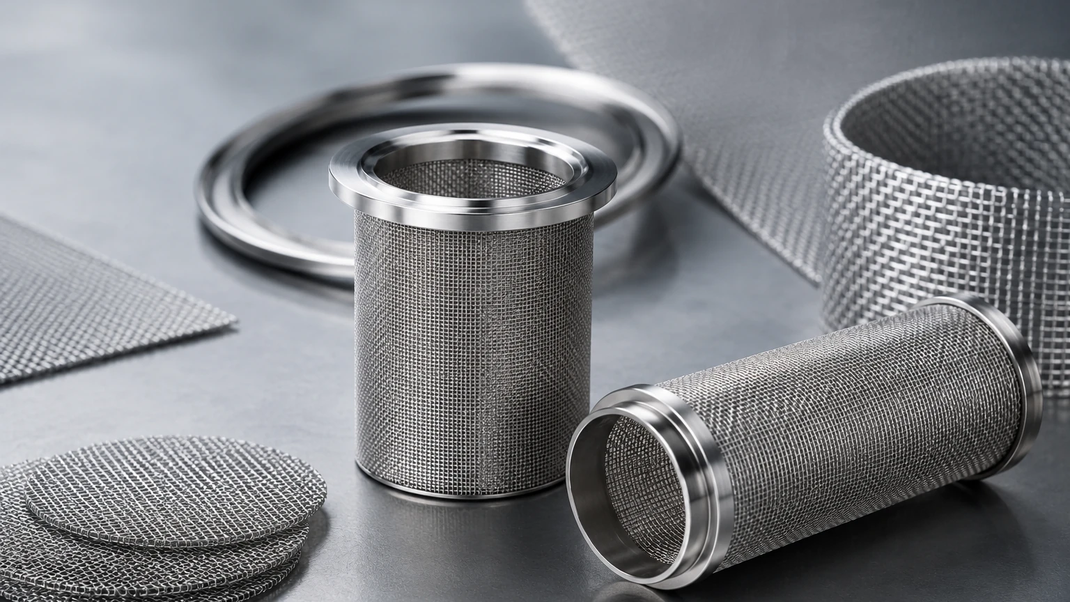
In many flash tank designs, a stainless steel wire mesh demister pad is installed near the steam outlet. As the steam passes through the dense matrix of the wire mesh, the liquid droplets, which have higher inertia than the vapor, collide with the wire surfaces and coalesce. Once the droplets grow large enough, they overcome the upward velocity of the steam and fall back into the liquid reservoir at the bottom of the tank. This ensures that the steam exiting the tank is nearly 100% dry.
Internal Strainers and Baffles
Flash tanks also act as a collection point for system debris, such as pipe scale and corrosion products. Stainless steel filter cartridges or internal strainers are frequently used to protect the condensate return pumps and downstream valves from these particulates. Because flash tanks deal with high temperatures and potentially corrosive condensate, the use of high-grade stainless steel (such as 304 or 316L) for these filtration components is non-negotiable for long-term durability.
Engineering Considerations for Flash Tank Sizing and Design
Sizing a flash tank is a balance between providing enough volume for separation and managing the cost and footprint of the vessel. There are two primary design configurations: vertical and horizontal.
Vertical Flash Tanks
Vertical tanks are the industry standard for most steam recovery applications. They offer a smaller footprint and are generally more efficient at liquid-vapor separation. The key design parameter for a vertical tank is the "disengagement velocity." If the upward velocity of the steam is too high, it will pull water droplets with it. Engineers typically design for a velocity that allows gravity to pull droplets back down. If space constraints require a smaller tank, the integration of a high-efficiency demister pad becomes even more critical to compensate for the reduced separation volume.
Horizontal Flash Tanks
Horizontal tanks are used when there are height restrictions or when very large volumes of condensate must be handled. While they provide a larger surface area for the liquid-vapor interface, they require careful internal baffling to prevent the incoming high-velocity condensate from creating turbulence that could re-entrain liquid into the steam stream.
Inlet and Outlet Sizing
The inlet piping must be sized to handle two-phase flow (the mixture of water and flash steam). If the inlet is too small, the resulting high velocity can cause erosion of the tank walls. The steam outlet must also be sized to keep pressure drop to a minimum, ensuring that the flash steam can reach its destination at the required pressure.
Material Selection and Corrosion Resistance in Steam Systems
Material choice is one of the most important factors in the longevity of a flash tank. While the shell of the tank may be constructed from carbon steel in some low-pressure industrial applications, the internal components and areas prone to erosion are almost always specified in stainless steel.
Industrial condensate can be aggressive. Dissolved oxygen and carbon dioxide in the condensate can lead to carbonic acid formation, which rapidly corrodes carbon steel. Furthermore, the high-velocity "flashing" action at the inlet can cause mechanical erosion.
Using stainless steel for internal filtration components, such as wire mesh filters and support grids, provides several advantages:
1. Corrosion Resistance: Stainless steel maintains its structural integrity in the presence of treated boiler water and aggressive condensate.
2. Temperature Stability: It retains its mechanical properties at the high temperatures common in steam systems.
3. Cleanliness: In industries like pharmaceutical or food and beverage processing, 316L stainless steel is required to prevent contamination of the "clean steam" used in sterilization or direct heating.
Operational Best Practices and Maintenance
To ensure a flash tank continues to operate at peak efficiency, regular maintenance of its internal filtration and separation components is necessary. Over time, the wire mesh demisters can become fouled with system scale or mineral deposits, especially in systems with poor water treatment. A fouled demister increases the pressure drop across the tank and can eventually lead to "slugging," where large volumes of water are pulled into the steam line.
Engineers should monitor the pressure differential across the flash tank. A significant increase often indicates that the internal filtration components or demisters need cleaning or replacement. When selecting replacement components, it is essential to work with a manufacturer that understands the specific demands of industrial filtration. Kaifil’s expertise in custom stainless steel filter cartridges and wire mesh solutions ensures that replacements meet the original engineering specifications for micron rating and flow capacity.
Additionally, the condensate discharge at the bottom of the tank must be managed. This is typically done through a float-operated steam trap or a level control valve. If the level control fails and the tank floods, the flash steam recovery process stops, and water is carried over into the steam system, potentially causing catastrophic damage to turbines or heat exchangers.
Conclusion: Optimizing Your Steam System
The flash tank is more than just a simple vessel; it is a precision-engineered component that sits at the heart of industrial energy recovery. By effectively separating flash steam from condensate, it allows facilities to recycle heat that would otherwise be wasted. However, the success of this recovery depends on the quality of the internal separation and filtration components.
When designing or retrofitting a steam system, engineers must prioritize material quality and filtration accuracy. High-performance stainless steel components are essential for resisting the harsh environment of high-pressure steam and ensuring the delivery of dry, clean vapor. For technical professionals seeking reliable, custom-manufactured filtration solutions to support their flash tank operations, reviewing the capabilities and product options available on the Kaifil Main Page provides a foundation for achieving long-term system efficiency and reliability.
