


Hydraulic Return Filter Housing
In industrial hydraulic systems, maintaining fluid cleanliness is the primary factor in ensuring component longevity and operational reliability. While suction and pressure filters play critical roles, the hydraulic return filter housing serves as the final barrier, capturing contaminants generated within the system before the fluid returns to the reservoir. This component is essential for preventing the accumulation of wear debris, which can lead to catastrophic pump failure or valve stiction. For engineers and procurement professionals, selecting the appropriate housing involves balancing flow dynamics, material compatibility, and structural integrity.
Understanding the Role of Return Line Filtration
The return line is the most common location for filtration in a hydraulic circuit. Because the fluid is returning to the tank, the operating pressures are significantly lower than those found in the high-pressure supply lines. This allows for the use of larger, more cost-effective filter elements that can achieve high dirt-holding capacities without the extreme wall thickness required for high-pressure housings.
However, the hydraulic return filter housing must still withstand specific stresses. Return lines often experience flow surges, especially in systems with large-diameter cylinders or rapid cycling. When a large cylinder retracts, the return flow can be several times the pump's output. The housing must be engineered to handle these transient flow peaks and the resulting back-pressure without compromising the seal or the structural integrity of the vessel.
Engineering Specifications for Hydraulic Return Filter Housings
When specifying a hydraulic return filter housing, several technical parameters must be evaluated to ensure the component meets the system's demands.
Flow Rate and Pressure Drop
The nominal flow rate of the housing should always exceed the maximum possible return flow of the system. A critical engineering metric is the "clean pressure drop" (ΔP). As fluid passes through the housing and the internal filter media, a natural resistance occurs. If the housing is undersized, the initial pressure drop will be high, leaving little room for the increase in pressure that occurs as the filter element collects contaminants. For most return line applications, a clean ΔP of less than 0.5 bar (7.2 psi) is recommended to prevent the bypass valve from opening prematurely.
Pressure Ratings
While return lines are generally low-pressure (often under 10 bar or 145 psi), the housing must be rated for the maximum expected surge pressure. In heavy-duty industrial environments, it is common to specify housings rated for 20 to 30 bar to provide a safety margin against hydraulic shock or "water hammer" effects that occur when valves close abruptly.
Material Selection: The Case for Stainless Steel
In many standard applications, aluminum or plastic housings are used due to their low cost. However, in demanding industrial environments—such as chemical processing, offshore oil and gas, or food and beverage production—stainless steel is the preferred material.
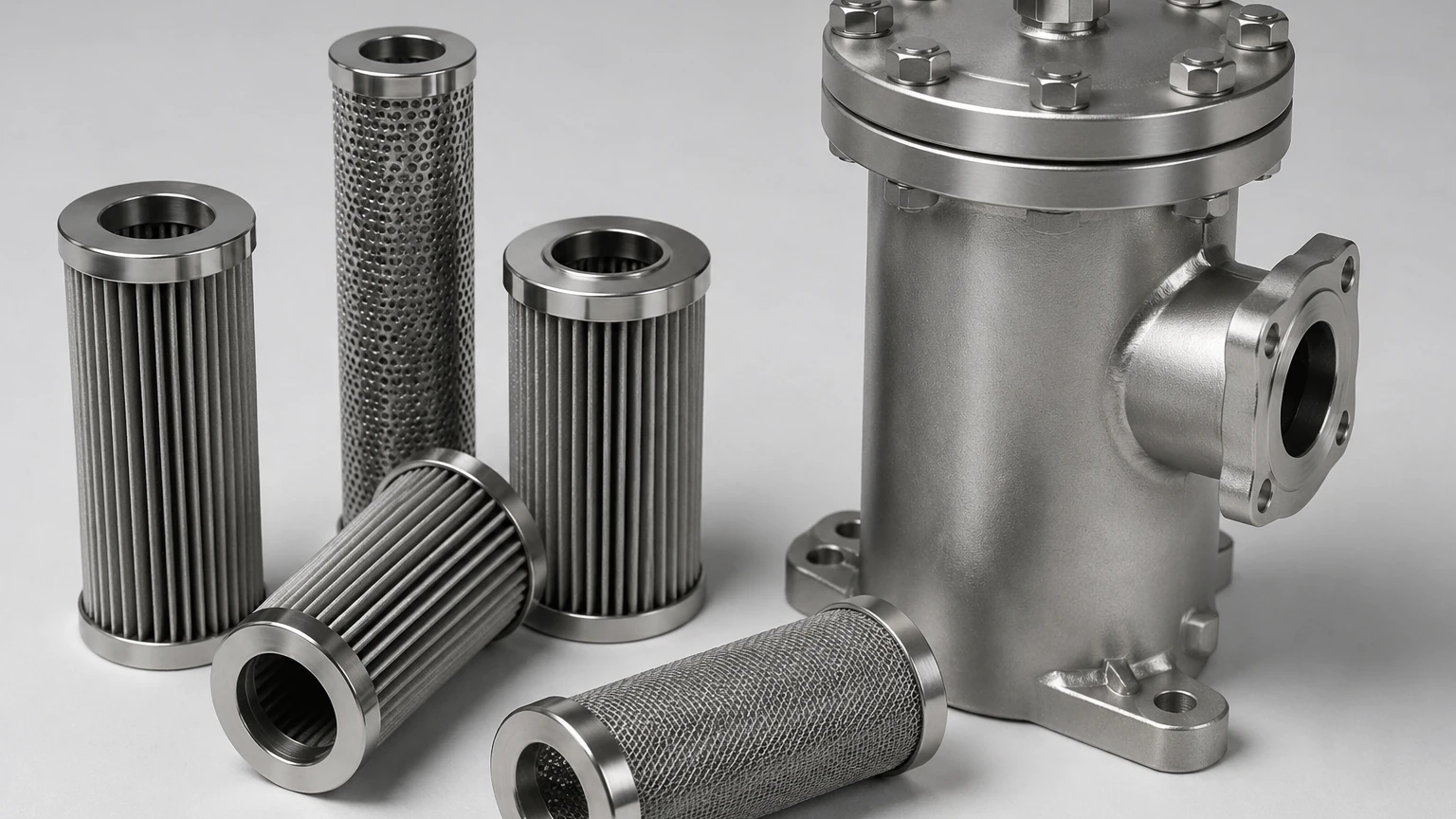
Stainless steel hydraulic return filter housings, typically constructed from 304 or 316L grades, offer superior corrosion resistance and durability. Unlike carbon steel, they do not require internal coatings that can flake off and contaminate the fluid. For applications involving synthetic fluids, high temperatures, or corrosive external environments, stainless steel provides a level of reliability that prevents long-term maintenance issues. Organizations focusing on high-performance filtration can explore specialized manufacturing options on the Main Page of the manufacturer’s site to understand how custom metal components are integrated into these systems.
Design Variations: Tank-Top vs. In-Line Housings
The physical configuration of the hydraulic return filter housing is determined by the reservoir design and available space.
Tank-Top Mounted Housings
This is the most common configuration for industrial power units. The housing is mounted directly onto the reservoir lid. The inlet port is located above the tank, while the outlet discharges directly into the fluid volume below the minimum oil level. This design minimizes external piping and simplifies element changes, as the filter can be accessed from the top of the tank without draining the return line.
In-Line Housings
In-line housings are installed directly into the return piping. These are often used when the reservoir is difficult to access or when the system layout requires the filter to be located closer to the work components. In-line housings must be robustly supported to prevent vibration from the piping from fatiguing the housing mounts.
Critical Components: Bypass Valves and Indicators
A hydraulic return filter housing is more than just a metal container; it is a functional safety device. Two critical integrated components are the bypass valve and the clogging indicator.
The Bypass Valve
Because the primary goal of a return filter is to protect the reservoir, the system must ensure that flow is never completely blocked. If the filter element becomes fully clogged with debris, the resulting back-pressure could rupture the element or cause upstream components to fail. A bypass valve is integrated into the housing to allow fluid to circumvent the filter media once a specific differential pressure (typically 1.5 to 3 bar) is reached. While this allows contaminated fluid into the tank, it prevents a total system over-pressurization.
Clogging Indicators
To prevent the system from running in bypass mode, housings are equipped with indicators. These can be visual (a color-coded gauge), electrical (a switch that sends a signal to a PLC), or electronic (providing a continuous 4-20mA signal). For automated industrial plants, electrical indicators are preferred as they allow for remote monitoring and scheduled maintenance before the bypass valve opens.
Integration and Customization for OEM Applications
For Original Equipment Manufacturers (OEMs), standard off-the-shelf housings may not always meet the specific spatial or performance requirements of a proprietary machine. Customization of the hydraulic return filter housing allows for optimized fluid dynamics and easier integration into compact assemblies.
Customization options often include:
* Porting Options: Selection of BSPP, NPT, or SAE flanged ports to match existing plumbing.
* Multi-Port Inlets: Allowing multiple return lines to enter a single housing, reducing the number of components on the tank.
* Internal Diffusers: Specialized outlet designs that reduce fluid velocity as it enters the tank, preventing aeration and foaming of the hydraulic oil.
* Material Specifications: Utilizing high-grade stainless steel wire mesh for the internal elements to ensure compatibility with aggressive hydraulic fluids or high-temperature operations.
Manufacturers like Kaifil specialize in these tailored solutions, providing precision-engineered metal components that satisfy specific industrial standards. By working with a manufacturer that understands the nuances of stainless steel fabrication, engineers can ensure that the housing will withstand the chemical and physical rigors of their specific application.
Maintenance and Longevity: Optimizing the Replacement Cycle
The total cost of ownership for a hydraulic return filter housing is largely dictated by the maintenance cycle of the internal elements. A well-designed housing facilitates quick and clean element changes, reducing machine downtime.
Monitoring Differential Pressure
The most effective way to determine the replacement cycle is through differential pressure monitoring. Replacing elements too early leads to unnecessary costs, while replacing them too late risks system contamination during bypass. Engineers should establish a baseline pressure drop when the system is at operating temperature and the fluid is clean. When the pressure drop reaches approximately 80% of the bypass valve setting, the element should be replaced.
Fluid Analysis
While the housing and filter protect the system, they also serve as a diagnostic tool. During an element change, the debris trapped within the media can be analyzed. The presence of large metallic flakes may indicate an impending pump failure, while the presence of silt-like particles might suggest an ingress of environmental dust through reservoir breathers.
Selection Guide for Engineers
When evaluating a hydraulic return filter housing for a new project or a system upgrade, use the following checklist to ensure all technical bases are covered:
1. Maximum System Flow: Ensure the housing can handle the peak return flow, not just the pump's nominal output.
2. Fluid Compatibility: Verify that the housing material and seals (Buna-N, Viton, or EPDM) are compatible with the hydraulic fluid (mineral oil, water-glycol, or synthetic esters).
3. Environmental Conditions: If the system is located in a coastal or chemical environment, specify stainless steel construction to prevent external corrosion.
4. Maintenance Access: Ensure there is sufficient "headroom" above a tank-top housing to remove the filter element.
5. Bypass Setting: Confirm the bypass valve pressure is higher than the expected back-pressure of the return line but lower than the collapse pressure of the filter element.
By adhering to these engineering principles, the hydraulic return filter housing becomes a reliable asset in the fluid power circuit, significantly reducing the risk of component wear and unplanned outages. For those requiring detailed technical support or custom-manufactured filtration components, further information can be found at https://www.kaifil.com/, where industrial filtration expertise meets advanced manufacturing capabilities.
