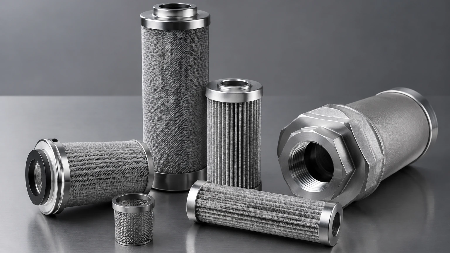
Hydraulic Return Line Filter
In the architecture of a high-performance hydraulic system, the hydraulic return line filter serves as the final stage of defense before fluid re-enters the reservoir. While suction filters protect the pump and pressure filters protect sensitive downstream valves, the return line filter is responsible for maintaining the overall cleanliness of the entire system by capturing wear debris generated by actuators, motors, and cylinders. For engineers and procurement specialists, selecting the correct filtration solution is not merely a matter of matching port sizes; it requires a deep understanding of fluid dynamics, material compatibility, and the specific contamination profiles of the application.
The Strategic Role of Return Line Filtration
The primary objective of a hydraulic return line filter is to ensure that the fluid returning to the tank meets or exceeds the required ISO 4406 cleanliness codes. Because hydraulic systems are dynamic, they constantly generate internal contaminants—metal shavings from pump wear, elastomer particles from seal degradation, and chemical by-products from fluid oxidation. If these contaminants are allowed to settle in the reservoir, they can be re-entrained into the suction line, leading to a "chain reaction of wear" that significantly shortens the lifespan of every component in the circuit.
Unlike pressure filters, which must withstand the full system operating pressure (often exceeding 3,000 to 5,000 PSI), return line filters operate at much lower pressures. However, they must be engineered to handle high flow volumes and potential flow surges. In many systems, the return flow can be substantially higher than the pump's output—for example, when a large-bore cylinder retracts rapidly. This necessitates a filter housing and element capable of managing these volumetric spikes without causing excessive back-pressure.
Engineering Considerations: Flow, Pressure, and Sizing
When specifying a hydraulic return line filter, the first technical hurdle is sizing for the "worst-case" flow scenario. Sizing a filter based solely on the pump's rated displacement is a common engineering oversight. A comprehensive analysis must account for the return-to-bore ratio of hydraulic cylinders. If a cylinder has a 2:1 area ratio, the return flow during retraction will be double the pump flow.
Failure to account for these surges leads to two primary issues:
1. High Pressure Drop (ΔP): Excessive resistance through the filter element increases back-pressure on the return side of actuators, which can lead to seal failure or reduced mechanical efficiency.
2. Frequent Bypass Activation: Most return line filters are equipped with a bypass valve to protect the housing from over-pressurization. If the filter is undersized, the bypass valve may open during flow surges, allowing unfiltered oil to dump directly into the reservoir.
For most industrial applications, it is recommended to size the filter so that the clean pressure drop does not exceed 0.3 to 0.5 bar (5 to 7 PSI) at the maximum expected flow rate. This provides a sufficient margin for the increase in ΔP as the filter element becomes loaded with contaminants.
Material Selection: The Case for Stainless Steel
While disposable cellulose or synthetic glass fiber elements are common in light-duty applications, demanding industrial environments often require the durability and precision of stainless steel. As a specialized manufacturer, Kaifil provides advanced stainless steel wire mesh and sintered metal fiber solutions that offer several technical advantages over traditional media.
Chemical and Thermal Stability
Industrial hydraulic fluids are not limited to standard mineral oils. Systems operating with phosphate esters, water-glycols, or high-temperature synthetic fluids can degrade standard adhesives and media in disposable filters. Stainless steel elements, particularly those using 304 or 316L grades, offer near-universal chemical compatibility and can operate in temperature ranges far exceeding the limits of polymers.
Structural Integrity and Fatigue Resistance
Return lines are subject to cyclic flow and pressure pulsations. Disposable media can suffer from "media migration" or fatigue-induced cracking under these conditions. Sintered stainless steel wire mesh provides a rigid, fixed-pore structure that maintains its filtration efficiency even under mechanical stress. This ensures that the micron rating remains constant throughout the service life of the element.
Cleanability and Sustainability
In high-volume industrial settings, the total cost of ownership (TCO) is a critical metric. While the initial investment in a stainless steel hydraulic return line filter element is higher, its ability to be cleaned (via ultrasonic baths or back-flushing) and reused significantly reduces long-term operational costs and waste disposal concerns. For more information on customized metal filtration components, engineers can visit the Main Page to explore material specifications.
Understanding Filtration Efficiency: Beta Ratios and Micron Ratings
To accurately predict the performance of a hydraulic return line filter, engineers must look beyond the "nominal" micron rating. The industry standard for evaluating filter efficiency is the Multi-Pass Test (ISO 16889), which yields the Beta Ratio (β).
The Beta Ratio is defined as the number of particles of a given size upstream of the filter divided by the number of particles of the same size downstream. For example, a β10 = 200 rating means that for every 200 particles of 10 microns entering the filter, only one passes through. This equates to 99.5% efficiency.
In return line applications, a Beta ratio of βx(c) ≥ 1000 (99.9% efficiency) is often targeted for high-precision systems, while βx(c) ≥ 200 is standard for general industrial hydraulics. It is vital to confirm that the selected filter maintains this efficiency across the entire range of operating temperatures, as changes in fluid viscosity can impact particle capture mechanics.
Installation Best Practices: Tank-Top vs. In-Line
The physical placement of the hydraulic return line filter influences both maintenance accessibility and system protection.
* Tank-Top Mounting: This is the most common configuration for industrial power units. The filter housing is mounted directly on the reservoir lid, with the outlet tube extending below the minimum fluid level. This design prevents aeration of the oil and simplifies element replacement, as the housing is easily accessible.
* In-Line Mounting: In mobile equipment or compact industrial layouts, the filter may be mounted in the return piping itself. While this offers flexibility in positioning, it requires robust mounting brackets to withstand the vibration and mechanical loads of the plumbing.
Regardless of the mounting style, the filter should be positioned as close to the reservoir as possible. It is also critical to ensure that the return flow enters the reservoir below the oil level to prevent foaming, which can lead to pump cavitation and erratic actuator movement.
Maintenance and Condition Monitoring
A filter is only effective if it is serviced before it reaches its terminal pressure drop. Relying on fixed time intervals for filter changes is often inefficient, as contamination ingression rates vary based on duty cycles and environmental conditions.
Modern hydraulic return line filters should be equipped with differential pressure indicators. These can be:
* Visual Indicators: A pop-up button or color-coded gauge (Green/Yellow/Red) that allows maintenance personnel to check the filter status during routine walk-arounds.
* Electrical Switches: These provide a signal to the PLC or central control system when the element is nearing saturation. This is essential for automated plants where manual inspection is infrequent.
When the indicator signals that the filter is restricted, the element should be replaced or cleaned immediately. If the system is allowed to run with a clogged filter, the bypass valve will remain open, and the system will effectively operate without filtration, leading to rapid component wear.
Customization and OEM Integration
For original equipment manufacturers (OEMs), standard off-the-shelf filters may not meet the specific spatial or performance requirements of a proprietary machine design. Customization options often include:
* Custom Porting: Utilizing SAE, BSPP, or NPT threads, or even custom flange mounts to integrate seamlessly with existing manifolds.
* Integrated Valving: Combining the bypass valve, check valves, or thermal lockout valves within the filter head to reduce the number of leak points in the system.
* Specialized Media Layers: Layering different grades of stainless steel mesh to achieve a balance between high dirt-holding capacity and low initial pressure drop.
Kaifil specializes in these tailored solutions, working closely with engineering teams to develop filtration components that meet the rigorous demands of chemical processing, hydraulic power units, and heavy industrial machinery. By focusing on precision manufacturing and high-grade materials, Kaifil ensures that every Main Page product provides reliable, long-term service in the field.
Conclusion
The hydraulic return line filter is a fundamental component for maintaining fluid health and system reliability. By capturing the internal wear debris of the circuit, it prevents the accumulation of contaminants in the reservoir and protects the entire hydraulic investment. When selecting a filter, engineers must prioritize accurate flow sizing, high-efficiency Beta ratios, and material durability. For applications involving extreme temperatures, aggressive fluids, or a requirement for reusable components, stainless steel filtration solutions offer the technical performance necessary to ensure maximum uptime and reduced total cost of ownership.