


Sintered Filter Diagram
In industrial filtration, precision is not merely a goal but a requirement for operational stability. For engineers and procurement specialists, a sintered filter diagram serves as the primary technical blueprint for understanding how a filter will perform under specific thermal, chemical, and mechanical stresses. Sintered filters, known for their high structural integrity and precise pore distribution, are manufactured through a process of heat and pressure that fuses metal particles or wire mesh layers without melting them. This results in a robust, porous medium capable of handling demanding environments in chemical processing, pharmaceuticals, and hydraulic systems.
Understanding the nuances of a sintered filter diagram is essential for selecting the correct filtration media. These diagrams provide more than just a visual representation; they detail the internal architecture, layer composition, and flow dynamics that define the filter's efficiency and service life. This guide examines the technical components of these diagrams, the engineering considerations behind different sintered structures, and the critical factors to confirm before finalizing a custom filtration solution.
1. The Anatomy of a Sintered Filter Diagram
A comprehensive sintered filter diagram typically illustrates the cross-sectional view of the filter media. Unlike standard wire mesh, which may shift under high pressure, a sintered structure is fixed. The diagram highlights several key features:
Pore Structure and Distribution
In a diagram representing sintered metal powder, the pore structure is often depicted as a "tortuous path." This means the fluid does not travel in a straight line but through a complex network of interconnected voids. The diagram should specify the mean pore size and the distribution range, which determines the filter's ability to capture particles of specific micron ratings.
Layering and Gradient Density
For multi-layer sintered mesh filters, the diagram is crucial for identifying the function of each layer. A standard 5-layer sintered mesh diagram generally includes:
* The Control Layer: The primary filtration layer that determines the micron rating.
* The Protection Layer: Placed on the upstream side to protect the control layer from direct impact or abrasion.
* The Dispersion Layer: Ensures even fluid distribution across the control layer.
* Support Layers: Heavier mesh layers that provide the mechanical strength necessary to withstand high differential pressures.
Connection and Housing Interfaces
The diagram also details the mechanical interfaces, such as threaded fittings, flanges, or O-ring grooves. These are critical for ensuring a leak-proof seal within the industrial housing, particularly in high-pressure hydraulic or gas filtration applications.
2. Comparing Sintered Metal Mesh and Sintered Powder Diagrams
When reviewing a sintered filter diagram, it is important to distinguish between the two primary types of sintered media: metal mesh and metal powder. Each has distinct characteristics reflected in their technical drawings.
Sintered Wire Mesh Diagrams
These diagrams focus on the geometric arrangement of woven wires. The sintering process bonds the contact points of the wires, creating a rigid structure that maintains its pore size even under extreme pressure. Engineers look at these diagrams to verify the "open area" percentage, which directly correlates to flow capacity and pressure drop. Sintered mesh is often preferred for surface filtration where easy backwashing or cleaning is required.
Sintered Metal Powder Diagrams
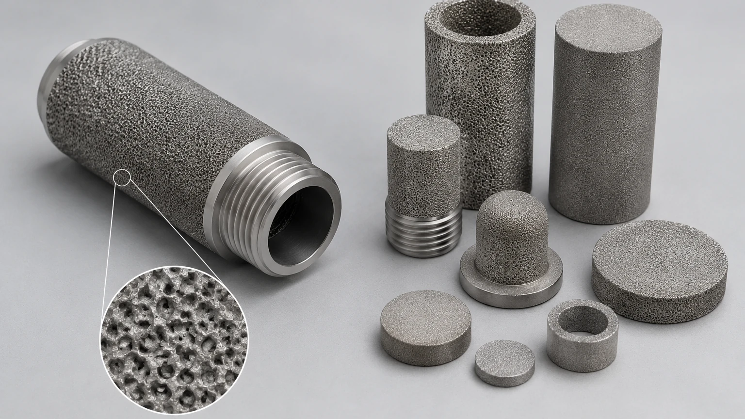
In contrast, a diagram for a sintered powder filter shows a more random, sponge-like structure. These filters are typically thicker and are used for depth filtration. The diagram will often indicate the thickness of the porous wall and the density of the material. Powder-based filters are ideal for applications requiring high filtration accuracy and the ability to hold a significant volume of contaminants before reaching the terminal pressure drop.
3. Engineering Considerations: Pore Size and Permeability
The primary purpose of analyzing a sintered filter diagram is to evaluate how the media will interact with the process fluid. Two metrics are paramount: micron rating and permeability.
Absolute vs. Nominal Micron Ratings
A technical diagram should specify whether the micron rating is absolute or nominal. In sintered media, the fixed pore structure allows for an absolute rating, meaning the filter will capture 99.9% of particles at or above the specified size. This is a critical distinction for pharmaceutical or food and beverage applications where contaminant bypass can lead to batch failure.
Permeability and Flow Resistance
Permeability refers to the ease with which a fluid passes through the porous medium. A diagram that includes a flow-vs-pressure drop curve (or references one) allows engineers to calculate the required surface area for a given flow rate. High-performance sintered filters aim to maximize permeability while maintaining a tight pore structure. If the diagram shows a very dense structure with limited thickness, the risk of rapid clogging increases, necessitating a larger filter footprint or more frequent cleaning cycles.
4. Material Selection and Chemical Compatibility
The material specified in a sintered filter diagram is as important as the physical structure. Most industrial sintered filters are manufactured from 316L stainless steel due to its excellent corrosion resistance and mechanical strength. However, for more aggressive environments, other alloys may be specified:
* 316L Stainless Steel: The standard for most chemical and water treatment applications.
* Hastelloy: Used for highly corrosive acidic environments.
* Inconel: Selected for high-temperature gas filtration where oxidation resistance is required.
* Monel: Preferred for applications involving hydrofluoric acid or seawater.
The diagram must clearly state the material grade to ensure compatibility with the process fluid and cleaning agents. Using an incompatible material can lead to intergranular corrosion, which weakens the sintered bonds and risks media migration into the downstream flow.
5. Customization and OEM Capabilities
Industrial filtration often requires bespoke solutions that off-the-shelf products cannot provide. A custom sintered filter diagram is the starting point for OEM development. At Kaifil, the focus is on engineering filtration components that meet specific operational parameters. Customization options often detailed in a diagram include:
* Variable Geometry: Sintered filters can be formed into tubes, discs, cones, or complex pleated cartridges to fit existing housing constraints.
* Reinforced Cores: For high-viscosity fluids or high-pressure pulses, an internal perforated core may be added to the diagram to prevent the sintered media from collapsing.
* Integrated End Caps: Welding end caps directly to the sintered media eliminates the need for adhesives, which can be a point of failure in high-temperature or chemically aggressive applications.
By working closely with manufacturers to refine these diagrams, engineering teams can optimize the total cost of ownership through extended filter life and reduced maintenance downtime. For more information on specific configurations, professionals can Review product options and application support to align their technical requirements with manufacturing capabilities.
6. Evaluation Criteria and Common Risks
When evaluating a sintered filter diagram during the procurement phase, several red flags and critical checkpoints should be considered to avoid operational failures.
Media Migration Risk
One of the greatest risks in low-quality sintered filters is media migration—where small particles of the filter itself break off and enter the process stream. A high-quality diagram and manufacturing specification will detail the sintering temperature and duration used to ensure a complete metallurgical bond. If the sintering is insufficient, the filter may look correct on a diagram but fail under mechanical vibration.
Effective Filtration Area (EFA)
Engineers must confirm the Effective Filtration Area shown in the diagram. This is the actual surface area available for fluid flow. In pleated sintered mesh filters, the EFA is significantly higher than in cylindrical filters of the same dimensions. A common mistake is underestimating the EFA required for high-solids-loading applications, leading to premature pressure spikes.
Cleaning and Regeneration
Sintered filters are an investment intended for long-term use. The diagram and accompanying data sheet should indicate the recommended cleaning methods, such as ultrasonic cleaning, backflushing, or chemical burnout. If a filter is designed with extremely deep pores (as seen in some powder diagrams), it may be harder to regenerate than a surface-filtering sintered mesh.
7. Confirming Technical Details Before Purchase
Before moving from the diagram stage to production, the intended audience—typically engineers and technical buyers—should confirm the following with the manufacturer:
1. Operating Temperature and Pressure: Ensure the sintered bonds and the chosen alloy can withstand the peak operating conditions, including any thermal shock events.
2. Bubble Point Testing: Confirm that each filter is tested according to ISO standards to verify the integrity of the sintered structure and the accuracy of the micron rating.
3. Welding Standards: Since end caps and fittings are often welded to the sintered media, the welding method (such as TIG or Plasma welding) should be specified to ensure it does not compromise the porous structure.
4. Differential Pressure Limits: Establish the maximum allowable differential pressure before the filter requires cleaning or replacement to prevent structural deformation.
Conclusion
A sintered filter diagram is more than a simple drawing; it is a critical engineering document that bridges the gap between application requirements and manufacturing reality. By carefully analyzing the layer structure, material specifications, and flow characteristics detailed in these diagrams, industrial professionals can select filtration solutions that offer the best balance of performance and durability. Whether the application involves delicate pharmaceutical separation or rugged hydraulic filtration, the precision of the sintered structure remains the foundation of efficient industrial processing. For those seeking to optimize their filtration systems, consulting with a manufacturer that specializes in custom stainless steel solutions is the most effective way to ensure that the final product meets the rigorous demands of the field. For further technical guidance and to explore custom filtration components, engineers are encouraged to visit the Main Page for comprehensive product specifications and support.
