


What Is a Flash Tank
In industrial steam and fluid management systems, efficiency is often determined by how well a facility recovers energy from high-pressure condensate. Central to this recovery process is a specialized pressure vessel known as a flash tank. Understanding what is a flash tank and how it integrates into a broader process flow is essential for engineers and plant managers looking to optimize thermal efficiency, reduce fuel costs, and protect downstream equipment from the effects of uncontrolled pressure drops.
A flash tank, also referred to as a flash vessel, is designed specifically to facilitate the separation of steam from high-pressure condensate when it is discharged into a lower-pressure environment. This process, known as "flashing," allows for the collection of low-pressure steam that would otherwise be lost to the atmosphere or wasted in a cooling process. By capturing this steam, industrial facilities can repurpose energy for heating, sterilization, or other secondary processes.
The Engineering Fundamentals of Flash Steam Generation
To answer the question of what is a flash tank from a technical perspective, one must first understand the thermodynamics of flash steam. When water is heated under pressure, its boiling point increases. For example, condensate at 100 psi (approximately 7 bar) exists at a temperature of roughly 338°F (170°C). If this high-pressure condensate is suddenly released into a vessel at 15 psi (1 bar), its boiling point instantly drops to 250°F (121°C).
The excess energy contained in the high-pressure liquid—the difference in the enthalpy of the saturated liquid at the two pressures—must be dissipated. This energy causes a portion of the water to spontaneously change phase from liquid to gas. This resulting vapor is what we call flash steam.
Without a dedicated flash tank, this phase change occurs violently within the piping, leading to water hammer, erosion, and significant energy loss. The flash tank provides the necessary volume and controlled environment to allow this separation to occur safely and efficiently. The amount of flash steam generated can be calculated using the formula:
% Flash Steam = (Hh – Hl) / Hvl x 100
Where:
* Hh is the enthalpy of saturated liquid at the higher pressure.
* Hl is the enthalpy of saturated liquid at the lower pressure.
* Hvl is the latent heat of evaporation at the lower pressure.
Components and Design Considerations of a Flash Tank
A flash tank is not merely a hollow cylinder; it is a precision-engineered component that must handle turbulent, two-phase flow. Several critical design elements ensure the vessel operates correctly:
Vessel Sizing and Velocity Control
The primary goal of a flash tank is to separate liquid from vapor. To achieve this, the upward velocity of the steam must be lower than the settling velocity of the water droplets. If the steam velocity is too high, it will carry water droplets into the steam header (entrainment), which can damage turbines or foul heat exchangers. Engineers typically design for a steam velocity of less than 10 feet per second (3 meters per second) within the vessel to ensure gravity-based separation.
Inlet and Internal Baffles
The inlet of the tank is often positioned tangentially or equipped with internal wear plates or baffles. This design helps dissipate the kinetic energy of the incoming high-pressure condensate and encourages the liquid to swirl against the tank walls, facilitating the release of steam bubbles from the liquid mass.
Level Control and Drainage
Since the tank receives a continuous flow of condensate, it must have a reliable method for discharging the remaining liquid. This is typically managed by a float-controlled steam trap or a level-control valve. Maintaining a consistent liquid level is vital; if the level is too high, the separation space is reduced; if it is too low, live steam may escape through the condensate outlet.
Industrial Applications and Energy Recovery
Flash tanks are ubiquitous in industries that rely on large-scale steam distribution, such as chemical processing, food and beverage production, and pharmaceutical manufacturing. Their primary role is energy conservation.
1. Boiler Blowdown Recovery: Boilers regularly discharge a portion of their water to remove dissolved solids. This blowdown is at the boiler's operating pressure and temperature. By routing blowdown through a flash tank, the resulting flash steam can be used to heat the boiler feed water in a deaerator, significantly reducing the amount of fresh fuel required.
2. Condensate Return Systems: In large facilities, high-pressure steam is used in various processes. The resulting condensate is often still at high pressure. Collecting this condensate in a flash tank allows the facility to generate low-pressure steam for space heating or low-temperature process jackets.
3. Pressure Reduction Stations: When steam must be stepped down from a high-pressure main to a low-pressure service line, a flash tank can manage the condensate that inevitably forms during the transition, ensuring the low-pressure side remains dry and efficient.
The Role of Filtration in Flash Tank Systems
While the flash tank handles the phase separation, the quality of the fluids involved is paramount to the longevity of the system. This is where high-performance filtration becomes a critical engineering consideration. Industrial steam systems are prone to "system crud"—a mixture of pipe scale, corrosion products (magnetite), and mineral deposits.
Protecting Downstream Equipment
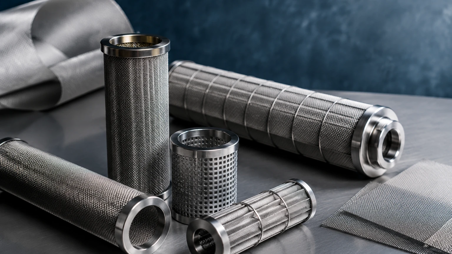
The flash steam produced in the tank is often sent to sensitive equipment like plate heat exchangers or control valves. If this steam carries over fine particulates, it can cause abrasive wear or clogging. Integrating stainless steel wire mesh filters or mist eliminators within or immediately after the flash tank ensures that the steam is not only dry but also clean.
Condensate Filtration
The liquid condensate remaining in the flash tank is a valuable resource, often containing expensive water treatment chemicals and thermal energy. However, it also collects the bulk of the system's particulates. Before this condensate is pumped back to the boiler or reused in a process, it must be filtered. Kaifil specializes in providing the custom stainless steel filtration solutions required for these demanding environments.
Using durable materials like 304 or 316L stainless steel for filter cartridges is essential because condensate can be chemically aggressive and high in temperature. Precision metal filter components can withstand the thermal cycling and pressure fluctuations inherent in flash tank operations, where standard polymer filters would fail. For technical specifications on filtration components suitable for steam and condensate systems, you can Review product options and application support on our Main Page.
Selection Criteria and Engineering Specifications
When specifying a flash tank and its associated filtration components, engineers must evaluate several key criteria to ensure long-term reliability and performance:
* Material Compatibility: While the tank shell might be carbon steel in some applications, internal components, especially filters and mist eliminators, should be made of stainless steel to resist the corrosive effects of carbonic acid often found in condensate.
* Pressure Rating: The tank must be designed and stamped according to relevant codes (such as ASME Section VIII) for the maximum possible pressure it might see, even if it normally operates at low pressure.
* Filtration Accuracy: When selecting filters for the condensate return or flash steam lines, the micron rating must be balanced against the allowable pressure drop. For steam applications, a coarser mesh might be used for scale removal, while condensate return lines might require finer filtration to protect boiler feed pumps.
* Customization Options: Every steam system has unique flow rates and pressure profiles. Standardized tanks often fail to provide optimal separation. Custom-designed vessels that account for specific inlet velocities and include tailored internal filtration elements provide the best ROI.
Common Risks and Operational Challenges
Failure to properly implement or maintain a flash tank system can lead to several industrial hazards and inefficiencies:
* Erosion-Corrosion: The high-velocity, two-phase flow at the inlet of a flash tank is highly erosive. Without proper internal protection or high-quality material selection, the tank wall can thin rapidly, leading to catastrophic failure.
* Priming and Carryover: If the tank is undersized or if the filtration/mist elimination components are fouled, water will be carried over into the steam system. This leads to water hammer, which can rupture pipes and damage expensive instrumentation.
* Steam Trap Failure: If the steam trap on the condensate outlet fails in the closed position, the tank will flood. If it fails open, live steam will blow through, negating the energy-saving purpose of the tank and potentially over-pressurizing the condensate return line.
Regular inspection of the tank internals and the replacement of filtration elements are necessary maintenance tasks. Using cleanable stainless steel wire mesh filters can reduce the total cost of ownership by eliminating the need for frequent disposable filter purchases.
Conclusion: Optimizing Your Thermal Strategy
Understanding what is a flash tank is the first step toward a more sustainable and cost-effective industrial operation. These vessels represent a critical junction where waste heat is transformed into a usable resource. However, the effectiveness of a flash tank is heavily dependent on the quality of its design and the protection of its components.
By integrating precision-engineered filtration and high-quality stainless steel components, engineers can ensure that their steam systems remain clean, efficient, and safe. Whether you are designing a new boiler blowdown recovery system or optimizing an existing condensate return loop, focusing on material durability and filtration performance is essential. For more information on custom filtration solutions designed for industrial environments, visit the Kaifil Main Page.
