


3ds Max Perforated Metal
In the realm of industrial design and mechanical engineering, the transition from a digital prototype to a physical component requires a deep understanding of manufacturing constraints and material properties. When engineers and designers utilize software like 3ds Max to model industrial filtration systems or architectural screens, the accuracy of the 3ds max perforated metal representation is critical. However, a visual model is only the first step. To ensure a design is functional, durable, and manufacturable, one must align digital specifications with the physical realities of Perforated & Expanded Metal production.
For B2B procurement teams and technical professionals, the challenge lies in translating these digital designs into high-performance stainless steel components that meet rigorous industrial standards. This guide explores the technical parameters, engineering considerations, and selection criteria necessary to bridge the gap between 3ds Max modeling and industrial manufacturing.
Bridging Digital Design and Industrial Reality
3ds Max is frequently used for high-fidelity visualization and preliminary structural layouts. In industrial contexts, such as the design of filter housings or support structures for wire mesh filters, the "perforated metal" component serves both functional and aesthetic purposes. In a digital environment, perforated metal is often represented using opacity maps or procedural textures to save computational resources. While this is sufficient for visual renders, it often bypasses the mechanical complexities of the material.
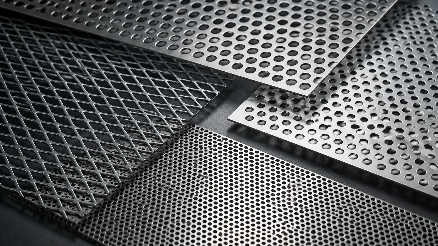
In physical manufacturing, perforated metal is created through a CNC punching process where sheets of stainless steel or other alloys are fed through a press. Expanded metal, conversely, is produced by slitting and stretching the metal simultaneously, creating a diamond-shaped pattern without any material waste. When moving from a 3ds Max model to a production order, engineers must specify exact hole diameters, center-to-center distances (pitch), and the resulting open area percentage. These factors directly influence the flow rate and pressure drop in filtration applications.
Technical Specifications for Perforated Metal Components
To move beyond a visual representation, engineers must define the geometric and material specifications that a manufacturer like Kaifil requires for production. The following parameters are essential for any industrial-grade perforated component:
Hole Patterns and Geometry
The most common pattern is the 60-degree staggered round hole, which provides the best balance of structural strength and open area. Other options include straight-row round holes, square holes, and slotted patterns. In 3ds Max, these are easily simulated, but in production, the choice of pattern affects the "bar" (the metal remaining between holes). If the bar is too thin, the material may warp during the punching process or fail under hydraulic pressure.
Open Area Calculation
The open area is the ratio of the total area of the holes to the total area of the sheet, expressed as a percentage. This is perhaps the most critical value for filtration. A higher open area reduces resistance to flow but decreases the structural integrity of the filter cartridge. Engineers must calculate this precisely rather than relying on the visual density of a 3ds Max texture map.
Material Selection: The Role of Stainless Steel
For most industrial applications—especially in chemical processing, pharmaceuticals, and food and beverage—stainless steel is the standard. Grades such as 304, 316, and 316L are preferred for their corrosion resistance and ability to withstand high temperatures. When specifying a 3ds max perforated metal component for a real-world environment, the material grade must be chosen based on the chemical compatibility of the fluid being filtered.
Modeling for Performance: Airflow and Filtration
When 3ds Max is used in conjunction with simulation tools, the geometry of the perforated metal becomes a variable in fluid dynamics. In industrial filtration, the perforated sheet often acts as a support cage for finer wire mesh. If the digital model does not accurately reflect the physical thickness and hole alignment, the simulation results for pressure drop will be skewed.
Structural Integrity and Support
In high-pressure hydraulic systems, the perforated metal core of a filter cartridge must resist collapsing. This requires a specific thickness-to-hole-diameter ratio. For instance, a common rule of thumb in the industry is that the sheet thickness should not exceed the hole diameter. If your 3ds Max model shows extremely small holes in a thick plate, it may be impossible to manufacture using standard punching methods, requiring more expensive laser or waterjet cutting.
Edge Configurations and Margins
A common oversight in digital modeling is the "margin"—the unperforated area around the edges of the sheet. For a filter to be welded into a cylinder or fitted into a housing, it requires solid edges. Designers must specify the width of these margins to ensure the component can be integrated into the final assembly without compromising the filtration surface.
Expanded Metal vs. Perforated Metal in Design
While the term "3ds max perforated metal" is often used as a catch-all, engineers must distinguish between perforated and expanded metal based on the application’s needs.
* Perforated Metal: Offers precise hole sizes and shapes. It is ideal for applications requiring specific filtration accuracy and high structural rigidity. It allows for complex margin designs and specific hole placements.
* Expanded Metal: Is more cost-effective because the manufacturing process involves no scrap. It provides a three-dimensional texture that can be useful for diffusing flow or providing grip. However, it is less precise for fine filtration and harder to clean in food-grade or pharmaceutical environments.
In 3ds Max, expanded metal requires a different modeling approach, often involving a "lattice" modifier or a specific diamond-shaped opacity map. Understanding these differences ensures that the procurement team selects the most efficient material for the project’s budget and performance requirements.
Key Evaluation Criteria for Industrial Procurement
When transitioning from a 3ds Max design to a B2B purchase order, the following criteria should be confirmed with the manufacturer to ensure the final product matches the engineering intent:
1. Dimensional Tolerances: Industrial filters often require tight tolerances to fit into precision-machined housings. Standard commercial tolerances may not be sufficient for high-end pharmaceutical or aerospace applications.
2. Surface Finish: Depending on the application, the metal may need to be electropolished, passivated, or degreased. For food and beverage applications, removing all burrs and ensuring a smooth surface is mandatory to prevent bacterial growth.
3. Flatness and Camber: The punching process can introduce internal stresses into the metal, causing it to curl or bow. If the part needs to be perfectly flat for a secondary assembly process, it must be leveled after perforation.
4. Secondary Operations: Does the perforated sheet need to be rolled into a tube, welded, or fitted with end caps? Manufacturers like Kaifil provide integrated OEM services that take the raw perforated sheet and transform it into a finished filter cartridge.
Avoiding Common Risks in Design-to-Production
One of the primary risks in using 3ds Max for industrial design is the creation of "impossible geometry." A digital model can easily feature holes that are too close together or patterns that violate the mechanical limits of the stainless steel grade.
Another risk is the failure to account for the "direction of flow." In expanded metal, the orientation of the diamonds can significantly affect how fluid or air passes through the screen. In a 3ds Max environment, it is easy to rotate a texture 90 degrees, but in production, the orientation is determined by the direction the coil is fed through the machine. Misalignment here can lead to unexpected turbulence or reduced efficiency in the final system.
To mitigate these risks, engineers should consult with manufacturing experts early in the design phase. Providing a 2D technical drawing alongside the 3ds Max visualization allows the manufacturer to verify the feasibility of the hole pattern, material thickness, and margin requirements.
Conclusion: From Visualization to Performance
Using 3ds Max for perforated metal design provides a powerful way to visualize complex industrial systems. However, the value of that visualization is directly tied to its adherence to physical manufacturing principles. By specifying the correct material grades, calculating precise open areas, and understanding the limitations of the punching and expansion processes, engineers can ensure their designs are both functional and cost-effective.
Whether you are designing a custom filter for a chemical plant or a protective screen for industrial machinery, the transition from digital model to physical product requires a partner with technical expertise in stainless steel fabrication. By focusing on the engineering realities of Perforated & Expanded Metal, you can move from a 3ds Max render to a high-performance industrial component that meets the most demanding application requirements.
