


Perforated Metal in Revit
In the realm of industrial facility design and mechanical engineering, the integration of precise component data into Building Information Modeling (BIM) workflows is essential for ensuring project accuracy and performance. For engineers and technical professionals utilizing Autodesk Revit, the representation of perforated metal components—ranging from architectural facades to critical industrial filtration elements—presents a unique set of challenges. This guide explores the technical methodologies for handling perforated metal in Revit, the engineering considerations that bridge the gap between digital models and physical manufacturing, and the criteria for selecting high-performance filtration solutions.
Approaches to Modeling Perforated Metal in Revit
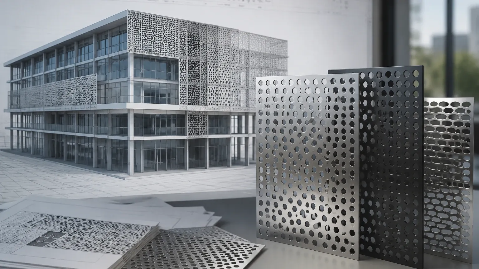
When designing systems that incorporate Perforated & Expanded Metal, engineers must decide between geometric accuracy and software performance. In Revit, modeling every individual hole in a large-scale industrial filter or screen can lead to excessive file sizes and significant latency during rendering and navigation. Therefore, two primary approaches are typically employed based on the project’s requirements.
1. Material-Based Representation (Opacity Maps)
For most industrial applications, such as large-scale chemical processing tanks or extensive ventilation screens, a material-based approach is the most efficient. This involves creating a custom material in Revit and applying a "Cutout" map. By using a high-resolution black-and-white image representing the hole pattern, the software simulates the appearance of perforations without creating actual geometry.
This method allows engineers to visualize the component and perform basic spatial coordination while maintaining a lightweight model. It is particularly useful when the primary goal is to represent the physical footprint and aesthetic of the metal without needing to calculate flow dynamics directly within the Revit environment.
2. Geometric Modeling for Precision Components
In cases where the perforated metal is a critical part of a precision assembly—such as a custom stainless steel filter cartridge or a specific hydraulic component—geometric modeling may be necessary. This involves using the "Void Forms" tool within a Revit Family to physically cut holes into a solid plate. While more resource-intensive, this method provides the exact geometric data needed for interference checking and high-detail assembly views.
When utilizing geometric modeling, it is vital to simplify the pattern where possible or use Revit’s "Detail Levels" (Coarse, Medium, Fine) to hide complex geometry when it is not strictly required for the current view. This ensures that the technical professional can work efficiently without sacrificing the integrity of the engineering data.
Material Properties and Engineering Specifications
The digital representation of perforated metal in Revit must eventually translate into a physical specification that meets industrial standards. For manufacturers like Kaifil, the transition from a BIM model to a production-ready component requires a deep understanding of material science and mechanical properties.
Stainless Steel Selection
In industrial filtration and chemical processing, material selection is the foundation of performance. Stainless steel grades such as 304 and 316L are frequently specified due to their superior corrosion resistance and durability. When defining materials for perforated metal in Revit, engineers should include metadata regarding the specific alloy, as this influences the weight, structural load-bearing capacity, and compatibility with various chemical agents.
Open Area Calculations
The "Open Area" percentage is perhaps the most critical technical metric for any perforated component. In a Revit model, this is often represented visually, but for procurement, it must be calculated with precision. The open area determines the flow rate, pressure drop, and filtration efficiency of the component. Whether the pattern is staggered or straight, the ratio of hole diameter to pitch must be clearly defined in the project documentation to ensure the manufactured part performs as intended.
Transitioning from BIM to Industrial Manufacturing
A successful project requires a seamless transition from the Revit environment to the manufacturing floor. This process involves more than just exporting a drawing; it requires a collaborative approach between the design team and the OEM manufacturer.
Customization and OEM Capabilities
Standard perforated sheets may not always meet the rigorous demands of specialized industrial applications. Customization is often required in terms of unique hole shapes (round, square, slotted, or hexagonal), specific margins (unperforated borders), and non-standard sheet thicknesses. When engineers work with a manufacturer like Kaifil, they can leverage advanced manufacturing capabilities to produce components that match the exact parameters defined in their Revit families.
Precision and Tolerances
While Revit models are mathematically perfect, physical manufacturing involves tolerances. For precision metal filter components, tolerances in hole diameter and spacing can affect the overall filtration accuracy. It is essential for purchasing teams to confirm the manufacturer’s ability to maintain tight tolerances, especially when the perforated metal serves as a support structure for fine wire mesh or other filtration media.
Performance Metrics in Perforated Filtration Components
For engineers focusing on filtration, the perforated metal is often the primary structural element of a filter cartridge or strainer. Understanding how these components perform under operational stress is key to preventing system failures.
Structural Integrity and Pressure Resistance
In hydraulic and high-pressure water treatment applications, perforated metal must withstand significant differential pressure. In Revit, structural analysis tools can be used to simulate loads on these components. The thickness of the metal and the bridge (the space between holes) are the primary factors contributing to the component’s strength. A common engineering mistake is maximizing the open area for flow while compromising the structural rigidity of the part, leading to deformation or collapse during high-pressure cycles.
Filtration Accuracy and Particle Retention
While the primary filtration is often handled by a secondary layer of wire mesh, the perforated metal provides the initial stage of debris removal and protects the finer media. Defining the hole size in the Revit model should align with the anticipated particle size distribution of the process fluid. If the holes are too large, the secondary mesh may be subjected to excessive wear; if they are too small, the system may experience premature clogging.
Evaluation Criteria for Procurement and OEM Partners
Before finalizing a specification for perforated metal in Revit and moving toward procurement, technical professionals should evaluate potential suppliers based on several key criteria. This ensures that the final product aligns with the technical requirements of the industrial application.
1. Quality Assurance and Material Certification
Industrial environments demand high-quality materials. Engineers should verify that the manufacturer provides material certifications (such as Mill Test Reports) to ensure the stainless steel meets the specified ASTM or ISO standards. This is particularly important in the pharmaceutical and food and beverage industries, where material purity and traceability are mandatory.
2. Manufacturing Versatility
Does the manufacturer have the capability to handle various forming processes? Perforated metal often needs to be rolled into cylinders, welded into cartridges, or pleated with other media. Choosing a partner with comprehensive OEM capabilities—from initial perforation to final assembly—reduces the risk of compatibility issues and streamlines the supply chain.
3. Technical Support and Engineering Collaboration
A reliable manufacturer acts as a technical resource. When an engineer is designing perforated metal in Revit, they may have questions regarding the feasibility of a specific pattern or the impact of a material choice on the total cost of ownership. A manufacturer that offers engineering guidance can help optimize the design for both performance and manufacturability.
Common Risks and Mitigation Strategies
Designing and specifying perforated metal involves navigating several potential pitfalls that can impact both the digital model and the physical installation.
* Software Performance Issues: As mentioned, over-modeling can crash Revit files. Mitigation: Use nested families with simplified geometry for high-level coordination and detailed geometry only for specific shop drawings.
* Moire Patterns in Visualizations: In Revit renderings, tight perforation patterns can create distracting visual artifacts known as Moire patterns. Mitigation: Adjust the scale of the cutout map or use a solid color with a transparency setting for general 3D views.
* Corrosion in Harsh Environments: Specifying the wrong grade of stainless steel for a chemical processing application can lead to rapid pitting and failure. Mitigation: Consult with material experts at the manufacturing stage to ensure the alloy is compatible with the specific chemical profile of the application.
* Inaccurate Flow Data: Relying solely on visual representations in Revit without performing rigorous open area calculations can lead to undersized filtration systems. Mitigation: Use dedicated engineering formulas to verify that the specified hole pattern meets the required flow velocity and pressure drop limits.
Conclusion: From Digital Design to Industrial Reality
Integrating perforated metal in Revit is a critical step in the modern industrial design process. By balancing the need for visual detail with the practicalities of software performance, and by grounding digital specifications in the realities of manufacturing, engineers can ensure that their designs translate into reliable, high-performance components.
Whether the application involves complex chemical filtration, hydraulic systems, or industrial water treatment, the success of the project depends on the synergy between precise design and expert manufacturing. By selecting a partner with extensive experience in Perforated & Expanded Metal and custom filtration solutions, engineering teams can achieve the durability, accuracy, and efficiency required for demanding industrial environments. The transition from a Revit model to a physical stainless steel component is a journey of technical precision, where every hole, margin, and material choice contributes to the overall integrity of the industrial system.
