


Perforated Metal Material Revit
In the realm of industrial design and architectural engineering, the integration of precise digital models with physical manufacturing capabilities is essential for project success. For engineers and specifiers working within Building Information Modeling (BIM) environments, specifically Autodesk Revit, creating an accurate perforated metal material revit representation is more than a visual requirement—it is a technical necessity. Whether designing custom filtration systems, protective screens, or structural components, the digital material must reflect the physical properties of the Perforated & Expanded Metal that will eventually be manufactured and installed.
This guide examines the technical considerations for modeling perforated metal within Revit, the engineering parameters that dictate performance, and the critical factors that bridge the gap between a digital material and a high-performance industrial filter component.
Understanding the Role of Perforated Metal in BIM
Perforated metal is a versatile material used extensively in industrial filtration, chemical processing, and HVAC systems. In Revit, a "material" is a collection of settings that define how an object looks in a render, how it appears in a drawing (hatch patterns), and its physical properties (thermal and structural).
When dealing with perforated metal material revit configurations, engineers often face a choice between modeling the actual geometry of the holes or using a "cutout map" to simulate the perforations. For large-scale industrial applications, such as secondary containment screens or large-diameter filter housings, modeling every individual hole can lead to significant software performance degradation. Therefore, a technical understanding of how to leverage material textures and transparency maps while maintaining the underlying engineering data is vital.
Visual vs. Geometric Accuracy
For the purposes of a technical submittal or a complex assembly drawing, the material must accurately represent:
1. Hole Pattern: The arrangement of openings (staggered vs. straight).
2. Open Area: The ratio of holes to the total surface area, which directly impacts flow rates and pressure drops.
3. Material Gauge: The thickness of the sheet, which affects the structural integrity of the filter cartridge or screen.
Technical Parameters for Industrial Perforated Metal
Before a material is defined in Revit, the engineer must determine the specific requirements of the physical component. At Kaifil, we specialize in manufacturing perforated solutions that meet precise industrial tolerances. The following parameters are essential for both the digital model and the manufacturing specification:
1. Hole Shape and Size
Common shapes include round, square, and slotted. Round holes are the most common in filtration because they offer a high strength-to-weight ratio and are easier to manufacture with high precision. The diameter of the hole is a primary factor in determining what size particles the filter will capture.
2. Pitch and Pattern
The "pitch" is the distance from the center of one hole to the center of the adjacent hole. In a staggered pattern (usually 60 degrees), the holes are offset, providing the highest open area and uniform strength. A straight pattern aligns holes in rows and columns, which may be preferred for specific structural alignments but often results in lower open area percentages.
3. Open Area Percentage
This is perhaps the most critical calculation for any filtration or airflow application. The formula for a 60-degree staggered round hole pattern is:
Open Area % = (D² × 90.69) / P²
*(Where D = Hole Diameter and P = Pitch)*
In Revit, the material’s transparency or cutout map should be calibrated to match this percentage to ensure that light, air, or fluid simulations within the BIM environment remain accurate.
Creating an Effective Perforated Metal Material in Revit
To create a functional perforated metal material revit definition, follow these technical steps to ensure the model remains lightweight yet informative:
Using Cutout Maps
Instead of using the "Void" command to cut thousands of holes in a solid plate, use the "Cutout" property in the Revit Material Editor. This uses a black-and-white image (a map) where black represents the holes (transparent) and white represents the metal (opaque).
* Scaling: Ensure the scale of the cutout map in Revit matches the actual physical pitch of the metal. If the pitch is 5mm, the image tiling must be set to 5mm.
* Surface Patterns: Apply a model hatch pattern to the material that corresponds to the hole centers. This allows the holes to be visible in hidden line views and technical drawings without requiring a full render.
Defining Physical Properties
For industrial applications, the "Physical" tab in the Revit material browser should be populated with data for the specific alloy being used. Most industrial filters manufactured by Kaifil utilize Stainless Steel 304, 316, or 316L. Including the correct density, yield strength, and thermal conductivity ensures that any structural or thermal analysis performed on the model is grounded in reality.
Engineering Considerations: From Model to Manufacture
While a Revit model provides a visual and spatial representation, the transition to manufacturing requires a deeper look at the physical limitations of metal fabrication. When specifying Perforated & Expanded Metal, engineers must consider several factors that are often overlooked in the digital phase:
Margins and Unfinished Areas
In a digital model, it is easy to show perforations extending to the very edge of a sheet. In reality, perforated sheets usually require "margins"—solid areas around the edges—to facilitate welding and provide structural stability. If a filter cartridge needs to be seam-welded, a solid margin is essential for a clean, leak-proof joint. Engineers should specify these margins in their technical drawings to avoid manufacturing delays.
Flatness and Stress
The process of perforating metal introduces internal stresses into the material. As the punch strikes the metal, it can cause the sheet to curl or bow. At Kaifil, we use leveling processes to ensure that the finished product meets flatness requirements, but it is important for the designer to understand that high open-area percentages can make the material more susceptible to deformation during subsequent forming or welding.
Deburring and Surface Finish
In pharmaceutical or food-grade applications, the edges of the perforations must be free of burrs to prevent contamination and ensure easy cleaning. While a Revit model will not show burrs, the specification should include requirements for mechanical or chemical deburring and the desired surface finish (e.g., electropolishing or pickling).
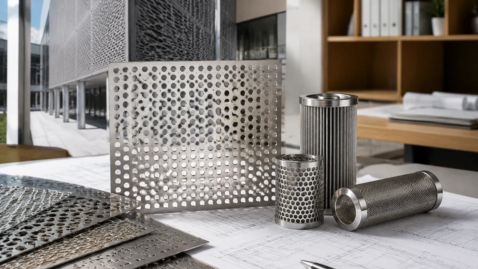
Material Selection: Stainless Steel in Filtration
Selecting the right alloy is critical for the longevity of the perforated component. In industrial filtration, stainless steel is the standard due to its corrosion resistance and durability.
* Stainless Steel 304: Suitable for general-purpose applications where moderate corrosion resistance is required.
* Stainless Steel 316/316L: Contains molybdenum, providing superior resistance to chlorides and pitting. This is the preferred choice for marine environments, chemical processing, and pharmaceutical applications.
* Specialty Alloys: For extreme temperatures or highly corrosive environments, alloys like Monel or Inconel may be specified, though these require specialized perforation techniques.
Common Risks in Specifying Perforated Metal
When bridging the gap between a perforated metal material revit design and a physical purchase, several risks can arise if communication is not clear:
1. Incompatible Hole Size to Thickness Ratio: A general rule of thumb in perforation is that the hole diameter should not be smaller than the material thickness (1:1 ratio). Attempting to punch 1mm holes in 3mm stainless steel can lead to frequent tool breakage and increased costs. If a finer filtration grade is needed, a multi-layer wire mesh or a different fabrication method may be required.
2. Over-Specification of Tolerances: While digital models are perfect, physical manufacturing has tolerances. Specifying unnecessarily tight tolerances for hole positions can significantly increase production costs without improving performance.
3. Ignoring Flow Direction: In some expanded metal applications, the orientation of the "diamonds" or openings can affect flow characteristics. The Revit model should clearly indicate the orientation if it is critical to the process.
Confirmation Checklist for Engineers and Purchasing Teams
Before moving from the Revit design phase to procurement, verify the following details with your manufacturer:
* Exact Material Grade: (e.g., SS316L for high-acid environments).
* Hole Pattern and Dimensions: Diameter, pitch, and stagger angle.
* Open Area Verification: Does the calculated open area meet the flow requirements of the system?
* Sheet Dimensions and Margins: Are there specific solid areas required for mounting or welding?
* Post-Processing Requirements: Does the part require degreasing, deburring, or specialized coating?
* Quantity and Lead Time: Custom perforation patterns may require specific tooling, which can affect delivery schedules.
Conclusion
An accurate perforated metal material revit representation is a powerful tool for modern industrial engineering. By combining the visual and data-rich capabilities of BIM with the practical manufacturing expertise of a specialist like Kaifil, project teams can ensure that their filtration and screening solutions are both high-performing and cost-effective.
When your project moves from the screen to the factory floor, having a partner that understands the nuances of Perforated & Expanded Metal is essential. Kaifil provides the technical support and manufacturing precision necessary to turn complex digital specifications into reliable, durable industrial components that meet the most demanding application requirements.
