


Perforated Metal Opacity Map
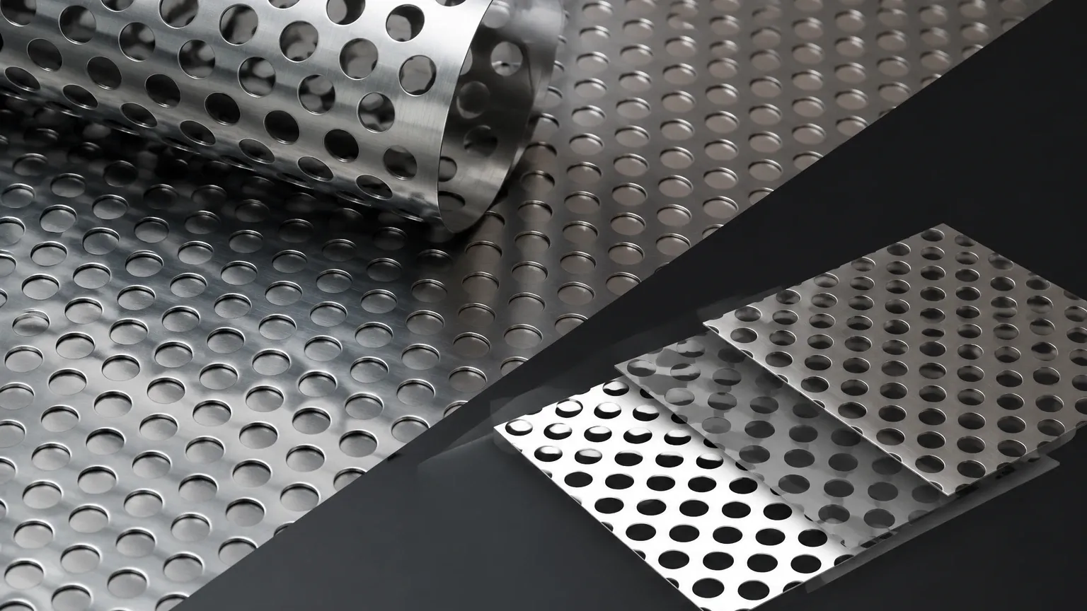
In industrial design, architectural engineering, and filtration system development, the transition from a conceptual model to a physical component requires precise data. A perforated metal opacity map serves as a critical digital tool in this process, bridging the gap between three-dimensional visualization and mechanical reality. While often associated with computer-aided design (CAD) and rendering, the technical principles behind these maps are rooted deeply in the physics of open area percentages, hole patterns, and material thickness.
For engineers and procurement specialists, understanding how a perforated metal opacity map relates to actual Perforated & Expanded Metal production is essential for ensuring that the final product meets functional requirements for airflow, light transmission, and structural integrity.
Understanding the Technical Relationship: Physical Perforation vs. Digital Opacity
A perforated metal opacity map is essentially a grayscale texture used in digital modeling to define which parts of a surface are solid (opaque) and which are holes (transparent). In a B2B context, particularly for filtration and industrial guarding, this map is more than a visual aid; it is a representation of the "Open Area Percentage."
The open area is the ratio of the total area of the holes to the total area of the sheet, expressed as a percentage. For example, if a stainless steel filter screen is specified with a 40% open area, the corresponding opacity map must accurately reflect this ratio to simulate performance characteristics like pressure drop or light diffusion. If the digital map does not align with the physical manufacturing capabilities, the resulting component may fail to meet the engineering tolerances required for high-pressure hydraulic systems or chemical processing environments.
Critical Parameters in Perforated & Expanded Metal Specification
When transitioning from a digital design or an opacity map to a physical product, several mechanical variables must be defined. These variables dictate the performance of the filter or structural component.
1. Hole Shape and Geometry
The geometry of the perforation affects both the opacity map's complexity and the metal's mechanical behavior. Common shapes include:
* Round Holes: The most standard and cost-effective option, providing high structural strength and uniform distribution of stress.
* Square Holes: Often used when a higher open area is required, though they may offer less structural rigidity than round patterns.
* Slotted Holes: Ideal for sifting and grading applications where the direction of flow or material movement is a factor.
* Hexagonal (Honeycomb) Holes: Provide the maximum possible open area while maintaining significant strength, frequently used in high-end filtration and ventilation.
2. Pitch and Pattern Arrangement
The "pitch" is the distance from the center of one hole to the center of the adjacent hole. The arrangement—whether staggered or straight—significantly impacts the "visual opacity" and the physical flow rate. A 60-degree staggered pattern is the most common industrial standard because it optimizes the hole density and maintains the structural integrity of the metal web (the material remaining between the holes).
3. Material Thickness (Gauge)
While an opacity map is two-dimensional, the physical metal has depth. The thickness of the material affects the "effective opacity" when viewed at an angle. In filtration, thicker materials provide higher pressure resistance but may require larger hole diameters to prevent clogging and ensure cleanability.
Engineering the Open Area: Calculations and Performance
For engineers, the perforated metal opacity map must be backed by rigorous calculation. The open area percentage determines the throughput of a filtration system. If the open area is too low, the system will experience excessive backpressure; if it is too high, the structural integrity of the filter cartridge may be compromised.
To calculate the open area for a standard 60-degree staggered round hole pattern, the following formula is applied:
OA = (D² × 90.69) / P²
Where:
* OA = Open Area Percentage
* D = Hole Diameter
* P = Pitch (Center-to-center distance)
In digital simulations using a perforated metal opacity map, these values allow designers to predict how much light or fluid will pass through the screen. In industrial filtration, Kaifil utilizes these calculations to ensure that custom filter components provide the exact micron rating and flow velocity required for specific chemical or food-grade applications.
Industrial Filtration and Structural Applications
Perforated and expanded metals are foundational components in various industrial sectors. The precision of the perforation pattern directly influences the efficiency of the following applications:
Filter Cartridge Support Cores
In high-pressure hydraulic or water treatment systems, pleated wire mesh filters often require a rigid internal or external support. A perforated metal cylinder acts as this core. The opacity map for such a part must prioritize the "web" strength to prevent the core from collapsing under differential pressure while maintaining enough open area to avoid restricting flow.
Acoustic and Thermal Guarding
In power generation and heavy machinery, perforated metals are used to dampen sound or protect sensitive components from heat. The opacity map helps engineers visualize the coverage. A lower open area (higher opacity) is generally better for sound attenuation, whereas a higher open area is necessary for heat dissipation.
Architectural and Safety Screening
For industrial walkways or machine guards, the opacity map is used to ensure that the mesh is "finger-safe" (preventing contact with moving parts) while still allowing operators to visually inspect the machinery. Here, the choice between perforated metal and expanded metal is crucial. Expanded metal is created by slitting and stretching the sheet, resulting in a diamond-shaped opening that provides excellent grip and strength-to-weight ratios.
Selecting Materials for Harsh Environments
A digital perforated metal opacity map does not account for chemical corrosion or thermal expansion, but the physical material selection does. Kaifil specializes in high-performance alloys to ensure longevity in demanding environments:
* Stainless Steel 304/304L: The standard for general industrial use, offering good corrosion resistance and weldability.
* Stainless Steel 316/316L: Contains molybdenum, making it superior for marine environments and chemical processing where chlorides are present.
* Duplex Stainless Steel: Used in high-stress, highly corrosive applications like offshore oil and gas filtration.
* Specialty Alloys: Including Monel or Inconel for extreme temperature or highly acidic conditions.
When specifying a product, engineers must confirm that the chosen material can be perforated to the desired specifications without inducing excessive work-hardening or micro-cracking in the metal webs.
Customization and Manufacturing Precision at Kaifil
At Kaifil, the production of Perforated & Expanded Metal components is a high-precision process. Unlike generic hardware-grade mesh, industrial filtration components require strict adherence to tolerances and surface finishes.
Precision Leveling and Burr Removal
The punching process used to create perforations can often leave the metal sheet slightly warped or with sharp burrs around the hole edges. For filtration applications, these burrs can trap contaminants or damage delicate filter media. Kaifil employs advanced leveling and deburring techniques to ensure that every sheet is flat and smooth, matching the clean lines of a digital opacity map.
Custom Margins and Blank Areas
One area where a standard opacity map often fails to represent reality is in the "margins." Industrial filters often require unperforated borders (margins) for welding or mounting into a housing. Kaifil can customize these margins on all four sides of a sheet or create "blank areas" within the perforated pattern to accommodate bolt holes or structural supports.
Technical Evaluation: What Engineers Should Confirm
Before moving from a design involving a perforated metal opacity map to a procurement order, technical teams should confirm the following:
1. Hole-to-Bar Ratio: Is the material between the holes (the bar/web) wide enough to support the intended load? A rule of thumb is that the bar width should be equal to or greater than the material thickness.
2. Direction of Stagger: In some applications, the direction of the staggered pattern relative to the flow or the sheet's length affects the structural rigidity.
3. End Patterns: Specify whether the pattern should be "finished" (symmetrical) or "unfinished" (randomly cut at the edges). Finished patterns are essential for aesthetic architectural applications and precise filter assembly.
4. Total Cost of Ownership: While high open-area patterns might seem efficient, they may require thicker, more expensive materials to maintain strength. Balancing these factors is key to a cost-effective solution.
Conclusion
The perforated metal opacity map is a vital starting point for modern industrial design, but its utility is defined by the physical constraints of metal fabrication. By understanding the relationship between hole geometry, open area calculations, and material properties, engineers can specify perforated and expanded metal products that deliver reliable, long-term performance in the field.
Kaifil continues to support global industries by providing customized, high-precision filtration and metal solutions. Whether you are designing a complex chemical filter or a robust industrial guard, ensuring your digital specifications align with manufacturing realities is the first step toward operational excellence.
