


Strainer Basket Diagram
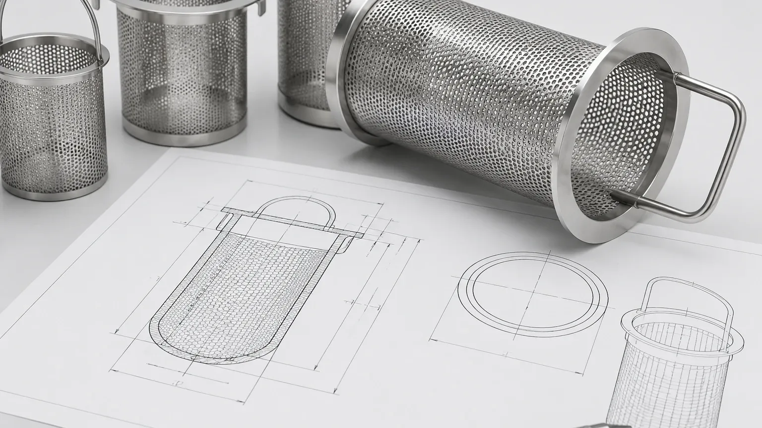
In industrial fluid handling, the efficiency of a filtration system is often determined by the structural integrity and design precision of its internal components. A strainer basket serves as the primary sacrificial barrier, protecting downstream equipment such as pumps, valves, and heat exchangers from particulate contamination. For engineers and procurement specialists, a technical strainer basket diagram is more than a simple visual aid; it is a critical engineering document that outlines flow dynamics, material thickness, structural reinforcement, and seating tolerances.
Understanding the nuances of these diagrams is essential for ensuring that a replacement or custom-engineered basket meets the rigorous demands of chemical processing, water treatment, or hydraulic applications. This guide examines the technical components of basket design, the engineering considerations behind the blueprints, and how to evaluate these specifications to optimize system uptime.
Anatomy of an Industrial Strainer Basket
A comprehensive strainer basket diagram typically illustrates several key components that work in unison to manage fluid velocity and pressure. While the exterior appearance may seem straightforward, the internal engineering determines the component's longevity and filtration efficiency.
1. The Seating Ring or Flange
Located at the top of the basket, the seating ring is the interface between the basket and the strainer housing. In a detailed diagram, this area specifies the gasket surface and the machining tolerances required to prevent "bypass." Bypass occurs when fluid escapes around the edges of the basket rather than passing through the media. For high-pressure applications, the diagram may specify a machined step or a heavy-duty flange to ensure a positive seal.
2. The Perforated Support Body
Most industrial baskets utilize a dual-layer construction. The outer layer is a perforated metal cylinder that provides the necessary mechanical strength to withstand differential pressure. The diagram will specify the hole diameter, the "pitch" (the distance between holes), and the thickness of the plate. Common perforation patterns include staggered or straight-line configurations, which directly impact the structural rigidity of the unit.
3. The Fine Mesh Liner
For applications requiring precise filtration, a fine wire mesh is lined inside the perforated support. The diagram must indicate the mesh count (the number of wires per linear inch) and the wire diameter. This layer is responsible for the actual particle retention. In high-performance Strainers & Baskets, the liner is often pleated to increase the surface area without enlarging the overall footprint of the basket.
4. The Lifting Handle
Often overlooked, the handle design is a vital part of the maintenance cycle. Diagrams show various configurations, including fixed bars, folding handles, or slanted handles designed to clear the housing cover. The handle must be robust enough to allow removal even when the basket is fully loaded with heavy debris.
Engineering Considerations in the Strainer Basket Diagram
When reviewing a strainer basket diagram, engineers must look beyond dimensions to evaluate how the design will perform under operational stress. Several variables dictate the reliability of the filtration component.
Open Area Ratio (OAR)
The Open Area Ratio is the relationship between the total open area of the basket's mesh/perforations and the cross-sectional area of the inlet pipe. A standard industrial design usually targets an OAR of at least 6:1. This ratio ensures that even as the basket begins to collect debris, the pressure drop ($ΔP$) remains within acceptable limits. A diagram that shows a restricted OAR may lead to frequent cleaning cycles and potential pump cavitation.
Flow Direction and Velocity
Most basket strainers are designed for "inside-to-out" flow. This ensures that debris is trapped within the basket, making it easy to remove during maintenance. The diagram should clearly indicate the intended flow path. If the fluid velocity is exceptionally high, the blueprint may include additional longitudinal or circumferential reinforcement ribs to prevent the mesh from collapsing or distorting.
Weld Integrity and Construction Methods
Technical drawings for industrial filters often specify the welding method. TIG (Tungsten Inert Gas) welding is preferred for stainless steel filtration components because it provides clean, strong joints without introducing slag. The diagram should highlight the seam locations, ensuring they are positioned to minimize flow resistance and structural weak points.
Material Selection and Compatibility
The materials specified in a strainer basket diagram are dictated by the chemical composition of the fluid and the operating temperature. At Kaifil, material selection is a foundational step in the OEM process to ensure long-term durability.
* Stainless Steel 304: The standard for general industrial use, offering good corrosion resistance and mechanical strength for water and mild chemical applications.
* Stainless Steel 316L: Preferred for pharmaceutical, food and beverage, and highly corrosive chemical environments. The "L" denotes low carbon content, which improves weldability and resistance to intergranular corrosion.
* Specialty Alloys: For extreme environments involving high salinity or aggressive acids, diagrams may call for Monel, Hastelloy, or Titanium.
Beyond the metal type, the diagram may also specify surface finishes. For example, an electropolished finish might be required for food-grade applications to eliminate microscopic pits where bacteria could reside.
Interpreting Dimensions for Replacement and Customization
One of the primary uses of a strainer basket diagram is to facilitate the procurement of replacement parts for existing housings. Accurate measurement is critical because even a 2mm discrepancy in height or flange diameter can lead to catastrophic bypass or the inability to close the housing lid.
Key dimensions to confirm on a diagram include:
1. Outside Diameter (OD) of the Flange: To ensure it sits correctly on the housing shoulder.
2. Overall Height: To ensure the basket does not bottom out before the seal is made.
3. Body Diameter: To allow for adequate clearance between the basket and the housing wall for fluid to circulate.
4. Bottom Design: Whether the basket has a flat bottom (maximizing volume) or a slanted/conical bottom (often used in specific flow configurations).
For custom OEM projects, the diagram serves as the definitive reference point for manufacturing. It allows engineers to adjust the filtration grade or structural reinforcement to solve specific problems, such as premature mesh failure due to high-viscosity fluids or abrasive particulates.
Maintenance and Total Cost of Ownership
A well-designed basket, as evidenced by a detailed technical diagram, directly impacts the total cost of ownership (TCO). Baskets that are engineered with a high OAR and robust reinforcement require less frequent cleaning and have a longer service life.
When evaluating a diagram for maintenance purposes, consider the ease of cleaning. A smooth interior surface with minimal "dead zones" allows for faster debris removal. Furthermore, the diagram should provide a reference for the "clean pressure drop." By knowing the baseline performance of a new basket, maintenance teams can set accurate thresholds for when a cleaning cycle is required, typically when the pressure drop reaches 5-10 psi over the clean state.
Conclusion: The Role of Technical Documentation in Procurement
For industrial professionals, the strainer basket diagram is the bridge between theoretical system design and physical operational reality. It provides the necessary data to verify compatibility, anticipate performance, and ensure safety. Whether you are sourcing standard replacements or developing a custom solution for a complex chemical process, the technical specifications found in the blueprint are your best defense against system inefficiency and equipment damage.
Kaifil specializes in translating these technical requirements into high-performance filtration hardware. By focusing on precision manufacturing and material integrity, we ensure that every basket—whether based on a standard design or a bespoke engineering diagram—delivers reliable performance in the most demanding industrial environments. When selecting your next filtration component, prioritize detailed technical documentation to ensure your system operates at peak efficiency with minimal downtime.
To explore specific configurations and engineering support for your filtration needs, you can Review product options and application support to find the ideal solution for your piping system.
