


Woven Wire Fence Diagram: A Technical Guide to Industrial Mesh Selection
In the realm of industrial engineering and filtration, a technical drawing or a woven wire fence diagram serves as more than just a visual aid; it is a precise blueprint that defines the mechanical and functional properties of a mesh structure. Whether used for heavy-duty industrial screening, architectural partitions, or high-precision liquid filtration, understanding the schematic representation of woven wire is essential for procurement teams and engineers.
At its core, Woven Wire Mesh is an engineered material. The performance of this material—its flow rate, particle retention, and structural integrity—is determined by the intersection of wire diameters, weave patterns, and material alloys. This article explores the technical components of mesh diagrams, the physics of different weave styles, and the critical factors engineers must confirm before finalizing a specification.
Understanding the Components of a Technical Mesh Diagram
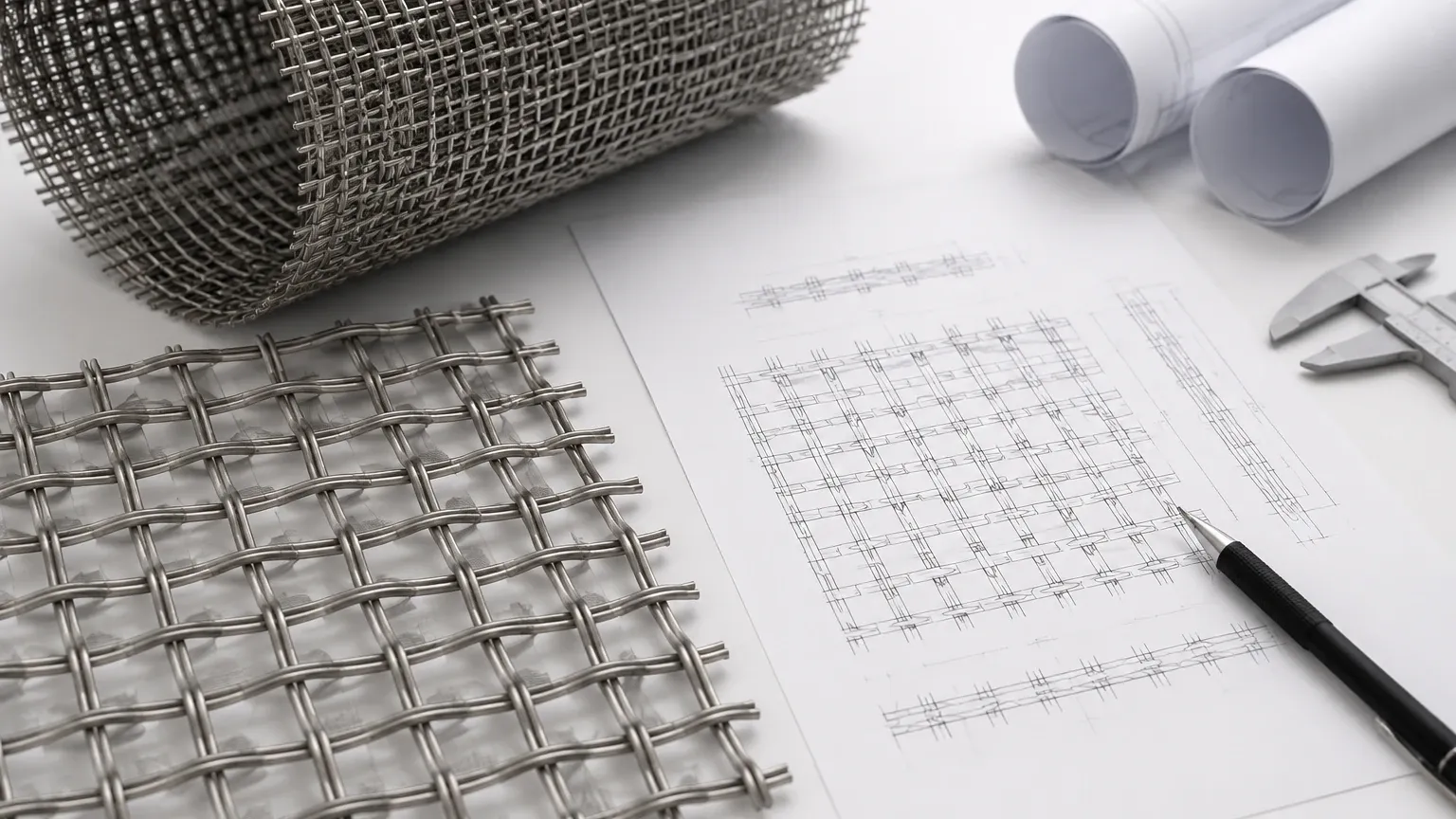
A professional woven wire fence diagram typically illustrates the cross-section and the surface view of the mesh. To interpret these diagrams correctly, one must understand the fundamental terminology used in the industry.
Warp and Shute Wires
The diagram identifies two primary wire directions. The warp wires are the wires running lengthwise in the roll as it is woven on the loom. The shute wires (also known as weft or fill wires) run crosswise, perpendicular to the warp. In a technical schematic, the spacing and diameter of these wires are the primary variables that dictate the mesh's performance.
Mesh Count and Aperture
The "Mesh Count" refers to the number of openings per linear inch, measured from the center of one wire to a point exactly one inch away. A diagram will often show a measurement scale to indicate this density. The aperture (or opening size) is the clear distance between two adjacent parallel wires. This is perhaps the most critical dimension for filtration applications, as it determines the maximum size of a particle that can pass through the medium.
The Crimp
Unlike simple welded wire, woven wire involves the mechanical interlocking of wires. The diagram will show the "crimp"—the undulation or bend in the wire that allows it to pass over and under the intersecting wires. Different crimp styles, such as plain crimp, lock crimp, or intercrimp, provide varying levels of stability and surface smoothness. For industrial "fencing" or partitions, a lock crimp diagram would show distinct notches where the wires intersect, ensuring the wires do not shift under mechanical stress.
Weave Patterns and Their Schematic Representations
The way wires are interlaced significantly impacts the mesh's characteristics. A technical diagram will clearly distinguish between these common weave styles:
1. Plain Weave
This is the most common and straightforward pattern. In a plain weave diagram, each shute wire passes alternately over and under each warp wire. This results in a square opening and is the standard for most general-purpose screening and filtration tasks. It offers the highest level of precision for aperture size in light-to-medium wire diameters.
2. Twill Weave
In a twill weave diagram, you will notice that each shute wire passes alternately over and under two warp wires. This pattern creates a diagonal appearance and allows for the use of heavier wires in a given mesh count than a plain weave would permit. This is particularly useful for high-pressure applications where increased mechanical strength is required without sacrificing filtration accuracy.
3. Dutch Weave (Plain and Twill)
Dutch weaves are designed for fine filtration. A diagram of a Dutch weave will show warp wires that are thicker than the shute wires. The shute wires are driven close together, creating a "zero-aperture" appearance on the surface, but providing complex, tortuous paths for the fluid to pass through. These diagrams are essential for understanding the depth-loading characteristics of a filter element.
Engineering Calculations Derived from the Diagram
When reviewing a woven wire fence diagram, engineers must perform specific calculations to ensure the mesh meets the project's operational requirements. The two most vital calculations are aperture size and percentage of open area.
Calculating Aperture
To verify the aperture size (A) when the mesh count (N) and wire diameter (D) are known, the following formula is used:
A = (1 / N) – D
For example, if a diagram specifies a 10-mesh count with a 0.025-inch wire diameter, the aperture would be 0.075 inches. This calculation is the first step in determining if the mesh is suitable for the target particle size.
Calculating Percentage of Open Area
The open area (OA) determines the flow capacity and pressure drop across the mesh. It is calculated as:
OA = (A / (A + D))² x 100
A higher percentage of open area indicates better flow but potentially lower structural rigidity. In industrial sectors like chemical processing or water treatment, balancing the open area with the mechanical strength of the wire is a key engineering challenge.
Material Selection: SS304 vs. SS316L
A technical diagram is incomplete without material specifications. For most industrial applications, stainless steel is the preferred material due to its durability and resistance to environmental stressors. Plain, twill and dutch woven wire mesh in SS304/316L — rolls, cut mesh and framed panels. Send mesh count or micron target for a technical quote.
* Type 304: The most common grade, offering excellent corrosion resistance in standard atmospheric conditions and many organic and inorganic chemicals. It is widely used in food processing and general industrial screening.
* Type 316L: Contains molybdenum, which provides superior resistance to chlorides and pitting. The "L" denotes low carbon, which improves weldability and prevents carbide precipitation during the welding of framed panels or filter cartridges. This is the standard for pharmaceutical and marine environments.
Beyond these, specialized alloys like Monel, Inconel, or Hastelloy may be specified in diagrams for extreme temperatures or highly acidic environments.
Common Risks in Mesh Selection and Procurement
Failure to accurately interpret or specify a woven wire fence diagram can lead to significant operational failures. Some common risks include:
1. Wire Migration: In low-quality weaves or inappropriate crimp styles, wires can shift, altering the aperture size and allowing oversized particles to pass through. Engineers should look for "lock crimp" or "intercrimp" specifications in diagrams for high-vibration environments.
2. Blinding and Plugging: If the wire diameter is too thick relative to the aperture, the mesh may "blind" (particles sticking to the surface) more easily. A diagram helps visualize the ratio of wire to opening to mitigate this risk.
3. Corrosion Fatigue: Selecting the wrong alloy (e.g., using 304 where 316L is required) can lead to rapid degradation of the mesh, resulting in system contamination and frequent replacement cycles.
4. Tolerances: Standard industrial mesh has specific tolerances for wire diameter and mesh count. Engineers must confirm whether their application requires "Market Grade," "Mill Grade," or "Bolting Cloth" tolerances, each of which has different schematic implications.
The Role of Customization in Industrial Filtration
While standard mesh rolls are available, many industrial applications require customized solutions. A woven wire fence diagram for a custom project might include details for:
* Edge Treatments: Hemmed edges, welded edges, or plastic-coated edges to prevent fraying and ensure safety during handling.
* Framed Panels: For use in vibratory separators or architectural partitions, the mesh is often tensioned and welded into a rigid frame.
* Multi-Layer Sintering: In advanced filtration, multiple layers of mesh (as shown in a layered diagram) are sintered together to combine fine filtration with high mechanical strength.
Kaifil specializes in translating these technical requirements into high-performance products. By working closely with a manufacturer that understands the nuances of the weaving process, engineers can ensure that the finished product aligns perfectly with the initial engineering diagram.
Conclusion: Confirming Technical Details Before Purchase
Before moving from the diagram stage to procurement, technical professionals should confirm several key points with their supplier:
* Is the mesh count verified? Ensure the count is consistent across the entire width of the roll.
* What is the wire diameter tolerance? Even small deviations can significantly impact the open area and flow rate.
* Is the material certified? Request material test reports (MTRs) to verify the alloy composition (e.g., SS316L).
* What is the intended environment? Discuss temperature, chemical exposure, and mechanical load to ensure the weave pattern and crimp style are appropriate.
By treating the woven wire fence diagram as a rigorous technical document rather than a simple illustration, purchasing teams can optimize their filtration processes, reduce maintenance costs, and ensure the longevity of their industrial equipment. For those seeking precision and reliability, selecting the right weave and material is the foundation of effective industrial performance.
