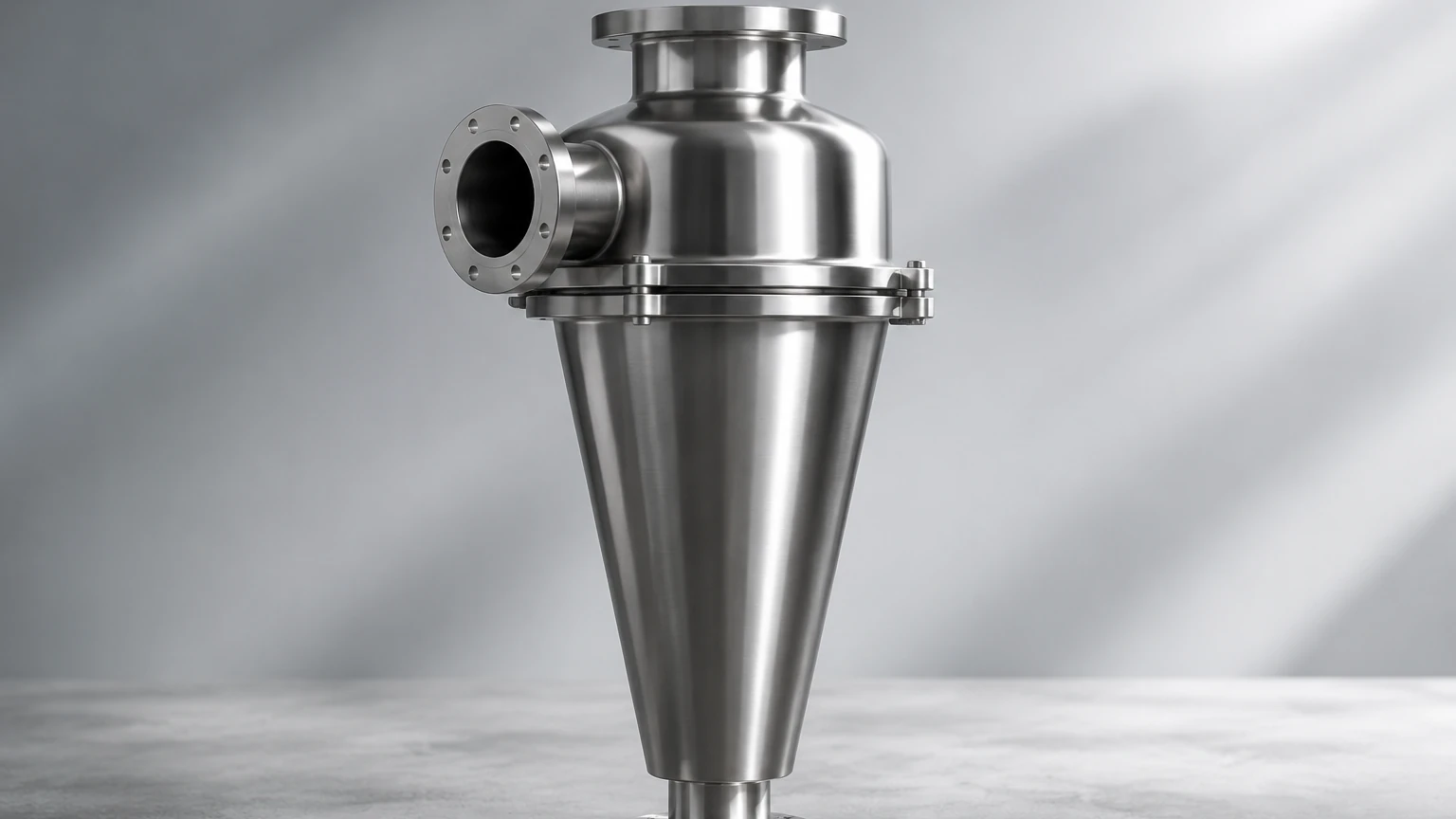
Cyclone Water Separator
In industrial fluid processing and compressed air systems, the presence of liquid water and bulk contaminants can lead to significant operational inefficiencies, equipment corrosion, and product spoilage. The cyclone water separator, also known as a centrifugal separator, serves as a critical mechanical solution for the removal of bulk liquids from gas or liquid streams. Unlike barrier-style filters that rely on a physical media to trap particles, the cyclone separator utilizes the principles of centrifugal force and gravity to achieve separation. For engineers and procurement teams, understanding the technical nuances of these components is essential for optimizing the lifespan of downstream filtration systems and ensuring process stability.
The Physics of Centrifugal Separation
The fundamental operation of a cyclone water separator is based on the conversion of linear fluid velocity into a high-speed rotational flow. This is typically achieved through a tangential or helical inlet design. As the fluid enters the cylindrical housing of the separator, it is forced into a downward spiral, creating a vortex.
Within this vortex, the heavier components—such as water droplets, oil mist, and solid particulates—possess greater inertia than the carrier gas or lighter fluid. The centrifugal force generated by the circular motion flings these heavier elements toward the inner walls of the separator housing. Once they strike the wall, they lose kinetic energy and coalesce into larger droplets. Gravity then pulls this liquid and debris down the walls into a collection chamber or sump located at the bottom of the unit.
Meanwhile, the cleaned fluid (often compressed air or process gas) reaches the bottom of the vortex and reverses direction, moving upward through the center of the separator in a secondary, narrower vortex. This fluid then exits through the "vortex finder" or outlet at the top. This mechanical process is highly efficient for removing bulk liquids (typically 99% of liquid water) without the need for moving parts or consumable filter elements.
Engineering Considerations for Material Selection
When selecting a cyclone water separator for industrial environments, material integrity is the primary factor determining the unit's longevity and performance. In sectors such as chemical processing, pharmaceuticals, and food and beverage, the separator must withstand both internal pressure and external environmental stressors.
Stainless steel, particularly grades 304 and 316L, is the industry standard for high-performance separation. As a specialist in custom stainless steel filtration solutions, Kaifil emphasizes the use of high-grade alloys to prevent oxidation and pitting. Unlike carbon steel or plastic alternatives, stainless steel separators offer:
1. Corrosion Resistance: Essential for handling moisture-laden air and aggressive chemical vapors that would otherwise compromise the structural integrity of the vessel.
2. Thermal Stability: Industrial processes often involve high-temperature steam or gas streams. Stainless steel maintains its mechanical properties across a wide temperature range.
3. Hygienic Compliance: In food and pharmaceutical applications, the non-porous surface of stainless steel prevents bacterial growth and facilitates easy sterilization (CIP/SIP processes).
Engineers must also consider the internal finish of the separator. A smooth internal surface reduces friction, which minimizes pressure drop and prevents the accumulation of sticky contaminants that could disrupt the vortex flow.
Performance Metrics: Efficiency vs. Pressure Drop
The performance of a cyclone water separator is evaluated based on two competing metrics: separation efficiency and pressure drop.
Separation efficiency refers to the percentage of liquid or solid mass removed from the stream. This is largely determined by the inlet velocity. Generally, higher velocities result in greater centrifugal force and better separation of smaller droplets. However, increased velocity also leads to a higher pressure drop (the difference in pressure between the inlet and the outlet).
An excessive pressure drop increases the energy consumption of the system's compressors or pumps. Therefore, sizing the separator correctly is a balancing act. If the separator is too small for the flow rate, the pressure drop will be too high; if it is too large, the fluid velocity may be insufficient to create a strong enough vortex, allowing moisture to carry over into the outlet. Technical teams should consult performance curves that plot efficiency against flow rates to ensure the chosen unit operates within its "sweet spot."
Integration with Downstream Filtration Systems
A cyclone water separator is rarely the sole filtration component in a high-purity system. Instead, it acts as a highly effective pre-filter. By removing the bulk of the liquid and large particulates, it protects more sensitive downstream components.
For instance, in a multi-stage filtration setup, the cyclone separator is placed upstream of high-precision Main Page components, such as coalescing filters or pleated stainless steel cartridges. Without a separator, these fine-mesh filters would quickly become saturated with liquid water (a condition known as "slugging"), leading to premature failure and high replacement costs.
By integrating a cyclone water separator as the first stage of defense, the service life of expensive secondary filter elements can be extended by 300% to 500%. This staged approach is standard practice in hydraulic systems and compressed air lines where moisture is the primary cause of component wear.
Application-Specific Design Variations
While the basic principle remains the same, the design of a cyclone water separator can be customized to meet specific industrial requirements.
* High-Pressure Environments: In hydraulic and oil-and-gas applications, separators must be designed as pressure vessels, often requiring ASME or PED certification. Wall thickness and weld quality are paramount in these designs.
* Steam Filtration: In steam systems, the separator must handle the high velocity and erosive nature of wet steam. Here, stainless steel construction is non-negotiable to prevent "wire drawing" and erosion of the internal components.
* Variable Flow Rates: Some systems experience fluctuating flow. In these cases, separators with internal baffles or modified inlet geometries can help maintain a stable vortex even when the flow rate drops below the nominal design point.
Kaifil provides customized filtration solutions that allow for these design adjustments, ensuring that the separator is optimized for the specific viscosity, density, and flow characteristics of the medium being processed.
Maintenance and Operational Reliability
One of the greatest advantages of the cyclone water separator is its low maintenance requirement. Since there are no filter media to clog and no moving parts to wear out, the unit can operate continuously for years with minimal intervention. However, the reliability of the system depends on the effective removal of the collected liquid from the sump.
If the collection chamber is allowed to overfill, the vortex can "re-entrain" the liquid, carrying it back into the outlet stream and defeating the purpose of the separator. To prevent this, industrial separators are typically equipped with one of three drainage options:
1. Manual Drains: Suitable for systems with very low moisture content where periodic manual blowing-down is feasible.
2. Float-Operated Automatic Drains: These use a mechanical float to open a valve when the liquid reaches a certain level. They require no power but can be prone to clogging if the fluid contains heavy solids.
3. Electronic Timed or Level-Sensing Drains: These provide the highest level of reliability, using sensors to discharge liquid without wasting compressed air or process gas.
Regular inspection of the drainage mechanism is the only significant maintenance task required to ensure the long-term efficiency of the separator.
Total Cost of Ownership (TCO) Analysis
When evaluating the procurement of a cyclone water separator, it is important to look beyond the initial purchase price. The Total Cost of Ownership (TCO) includes the unit cost, installation, energy costs associated with pressure drop, and the savings generated by protecting downstream equipment.
Because stainless steel separators from manufacturers like Kaifil are built for durability, they often have a service life exceeding 15–20 years. When compared to the recurring cost of replacing barrier filter elements or repairing moisture-damaged pneumatic tools, the return on investment (ROI) for a high-quality centrifugal separator is typically realized within the first year of operation.
For engineers, the decision to implement a cyclone water separator is a strategic move toward system stability. By removing the bulk of contaminants through mechanical force rather than surface-loading media, facilities can achieve a more predictable and cost-effective filtration process.
Whether the application involves protecting a large-scale chemical reactor or ensuring the quality of bottled beverages, the cyclone water separator remains a foundational technology in industrial fluid management. Its simplicity, combined with the material expertise of specialized manufacturers, provides a robust solution for the most demanding filtration challenges.