


Perforated Metal Vector
In the realm of industrial manufacturing and precision engineering, a perforated metal vector is far more than a simple graphic asset. It represents the foundational blueprint for high-performance components used in filtration, acoustic dampening, and structural support. For engineers and procurement specialists, understanding how these digital designs translate into physical Perforated & Expanded Metal products is essential for ensuring operational efficiency and long-term durability in demanding environments.
At Kaifil, we recognize that the precision of the initial design—often shared as a vector file—directly dictates the performance of the final stainless steel filter or metal component. This guide explores the technical relationship between digital vector specifications and physical manufacturing, providing actionable insights for selecting the right materials, patterns, and tolerances for industrial applications.
The Role of Vector Files in Precision Perforation
A perforated metal vector file (typically in formats like DXF, DWG, or AI) serves as the mathematical instruction set for CNC (Computer Numerical Control) punching machines and laser cutting systems. Unlike raster images, which are composed of pixels, vector graphics use paths defined by mathematical equations. This allows for infinite scaling without loss of resolution, which is critical when designing complex filtration systems where hole diameters may be measured in microns.
From an engineering perspective, the vector file provides the precise coordinates for:
* Hole Diameter: The exact size of the opening.
* Pitch/Center Distance: The distance between the centers of two adjacent holes.
* Pattern Orientation: Whether the holes are staggered (usually 60 degrees) or straight-row.
* Margins: The unperforated areas along the edges of the sheet required for welding or mounting.
When a manufacturer receives a perforated metal vector, it is integrated into the production workflow to ensure that the physical output matches the theoretical design with minimal deviation. This is particularly important for custom OEM projects where the filter must fit into a pre-existing housing with zero-tolerance errors.
Engineering Considerations: Translating Design to Reality
While a digital vector can depict any imaginable pattern, physical manufacturing is bound by the laws of material science and mechanical stress. Engineers must consider several factors when finalizing a design for production.
The Hole-to-Thickness Ratio
One of the most common challenges in translating a perforated metal vector to a physical product is the relationship between the hole diameter and the sheet thickness. As a general rule of thumb in the industry, the hole diameter should not be smaller than the thickness of the material. For example, if you are using a 2mm thick stainless steel sheet, the holes should ideally be 2mm or larger. Attempting to punch holes smaller than the material thickness increases the risk of tool breakage and can lead to structural deformities in the metal.
Open Area Calculations
The "open area" is the percentage of the sheet that is comprised of holes. This is a critical metric for filtration applications, as it determines the flow rate and pressure drop across the filter. A perforated metal vector allows engineers to calculate this precisely before a single sheet of metal is cut.
For a standard 60-degree staggered round hole pattern, the formula for open area is:
* OA = (D² × 90.69) / R²
* *Where D is the hole diameter and R is the center-to-center pitch.*
High open areas (above 50%) provide excellent flow but may compromise the structural integrity of the sheet. Conversely, low open areas provide high strength but may lead to excessive backpressure in hydraulic or chemical processing systems.
Comparing Perforated and Expanded Metal Geometries
When reviewing a design, it is important to distinguish between perforated metal and expanded metal, as they serve different functional purposes and require different vector approaches.
Perforated Metal
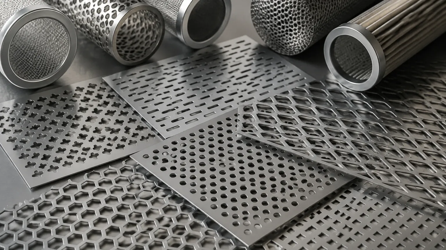
Perforated metal is created by punching a series of holes into a solid sheet. This process allows for extreme precision in hole shape (round, square, slotted, or decorative) and spacing. It is the preferred choice for applications requiring specific filtration ratings or precise acoustic control. Because the material is removed during the punching process, the resulting sheet maintains a flat profile, making it easier to roll into filter cartridges or weld into assemblies.
Expanded Metal
Expanded metal is produced by simultaneously slitting and stretching a sheet of metal. This creates diamond-shaped openings without any material waste. While a perforated metal vector for expanded metal focuses on the "long way of design" (LWD) and "short way of design" (SWD), the physical product has a three-dimensional texture. Expanded metal is often used for support structures, such as the inner cores of high-pressure filter cartridges, or for industrial walkways where slip resistance and high strength-to-weight ratios are required.
Material Selection for Industrial Filtration
The longevity of a perforated or expanded metal component is largely determined by the material used. In industrial environments where corrosion, high temperatures, and chemical exposure are common, stainless steel is the gold standard.
1. 304 Stainless Steel: The most common grade, offering excellent formability and good corrosion resistance for food processing, water treatment, and general industrial use.
2. 316L Stainless Steel: Contains molybdenum, providing superior resistance to chlorides and pitting. This is essential for pharmaceutical applications, marine environments, and aggressive chemical processing.
3. Specialty Alloys: For extreme environments involving high heat or highly acidic fluids, alloys such as Monel, Inconel, or Hastelloy may be specified in the design phase.
When finalizing your perforated metal vector, ensure that the material thickness and grade are clearly specified to avoid performance failures in the field.
Customization and OEM Capabilities
Standard off-the-shelf perforated sheets rarely meet the specific needs of complex engineering projects. This is where custom OEM capabilities become vital. A professional manufacturer like Kaifil can take a custom perforated metal vector and produce components that are tailored to the application.
Custom Hole Patterns
Beyond standard round and square holes, vectors can define complex patterns such as hexagonal (honeycomb) for maximum open area, or slotted holes for specific particle separation in vibrating screens. These custom patterns can be optimized for specific flow dynamics or to match the aesthetic requirements of architectural projects.
Secondary Processing
A vector-based design is often just the first step. To create a finished filtration solution, the perforated sheet may undergo:
* Rolling and Welding: Forming the sheet into a cylinder for use as a filter cartridge.
* Degreasing and Passivation: Removing manufacturing oils and enhancing the protective oxide layer of stainless steel.
* Edge Trimming and Notching: Ensuring the component fits perfectly into its final assembly.
Evaluating Risks in the Design Process
Inaccurate vector files or a lack of understanding of manufacturing constraints can lead to several risks during the procurement process:
* Pattern Distortion: If the pitch is too small relative to the hole size, the "bridge" (the metal between holes) may buckle during the punching process.
* Burr Formation: Inadequate tool maintenance or incorrect material selection can lead to burrs on the exit side of the hole, which can trap contaminants in a filtration system or cause safety hazards during handling.
* Tolerance Accumulation: Over long sheets, small deviations in pitch can add up, leading to a significant misalignment at the end of the piece. High-precision manufacturing ensures these tolerances are kept within strict limits (e.g., +/- 0.1mm).
To mitigate these risks, it is recommended to consult with the manufacturer’s engineering team during the design phase. Providing a clean, accurate perforated metal vector allows the manufacturer to perform a "design for manufacturability" (DFM) review, identifying potential issues before production begins.
Total Cost of Ownership and Procurement Guidance
When purchasing Perforated & Expanded Metal components, the initial price per unit is only one part of the total cost of ownership (TCO). Engineers and purchasing teams should also consider:
* Durability and Lifespan: A higher-grade stainless steel may have a higher upfront cost but will significantly reduce replacement frequency and downtime in corrosive environments.
* Filtration Efficiency: A precisely engineered hole pattern reduces energy consumption by minimizing pressure drop across the system.
* Ease of Maintenance: Smooth, burr-free perforations are easier to clean (backwash) and maintain, extending the life of the filter.
Before taking the next step in your project, confirm the following with your supplier:
1. Material Certification: Ensure the stainless steel meets the required ASTM or ISO standards.
2. Dimensional Accuracy: Verify that the manufacturer can hold the tolerances specified in your vector file.
3. Production Capacity: Ensure the supplier can handle both small-scale prototyping and large-volume production runs.
Conclusion
The use of a perforated metal vector is a critical bridge between digital engineering and physical performance. By understanding the technical nuances of hole patterns, material properties, and manufacturing constraints, engineers can design filtration and structural components that are both efficient and durable.
Whether you are developing a new chemical processing filter or a custom hydraulic component, the precision of your design—and the expertise of your manufacturing partner—will determine the success of your application. At Kaifil, we combine advanced manufacturing capabilities with deep engineering experience to turn your vector designs into high-performance industrial solutions.
