


Disc Filter Dwg
In the precision-driven world of industrial filtration, the technical drawing—often referred to by its file format, a disc filter dwg—serves as the foundational blueprint for manufacturing high-performance components. For engineers and procurement specialists, these drawings are more than just digital files; they are the definitive source of truth for dimensional accuracy, material composition, and structural integrity. Whether used in polymer melt filtration, chemical processing, or hydraulic systems, Filter Discs & Packs must be engineered to exacting standards to ensure system reliability and process efficiency.
Understanding the nuances of a disc filter design requires a deep dive into the technical parameters that define its performance. From the selection of wire mesh weaves to the method of edge reinforcement, every detail captured in a CAD drawing impacts the final product’s ability to withstand pressure, resist corrosion, and provide consistent filtration accuracy.
The Role of Technical Drawings in Filtration Engineering
A technical drawing, specifically a disc filter dwg, is the primary communication tool between the design engineer and the manufacturer. In B2B industrial environments, where components must fit into complex machinery like extruders or high-pressure valves, a lack of precision can lead to catastrophic system failure or costly downtime.
When reviewing or creating a drawing for filter discs, several critical elements must be documented:
1. Outer and Inner Diameters (OD/ID): Precise measurements are essential for ensuring a snug fit within the filter housing. Even a fraction of a millimeter in deviation can lead to bypass, where unfiltered fluid escapes around the edges of the disc.
2. Layer Configuration: Many industrial applications require multi-layer filter packs. The drawing must specify the sequence of mesh counts, ranging from coarse support layers to fine filtration media.
3. Material Specifications: The drawing should clearly state the grade of stainless steel (e.g., AISI 304, 316, or 316L) to ensure chemical compatibility with the process fluid.
4. Tolerance Levels: Industrial filters often operate under high pressure. Specifying tight tolerances ensures that the filter remains seated correctly during thermal expansion or pressure surges.
Material Selection and Mesh Characteristics
The performance of Filter Discs & Packs is largely determined by the characteristics of the wire mesh used in their construction. Stainless steel is the industry standard due to its exceptional durability and resistance to oxidation. However, the specific weave type chosen for the disc filter dwg will dictate the flow rate and particle retention capabilities.
Common Weave Types
* Plain Weave: The most common and economical option, offering a straightforward over-under pattern. It is ideal for general filtration where high flow rates are prioritized over extreme precision.
* Twill Weave: This pattern allows for thicker wires and higher mesh counts, providing increased strength and better filtration of fine particles.
* Dutch Weave (Plain and Twill): These weaves feature a higher density of wires in one direction, resulting in a tortuous path for particles. This is the preferred choice for high-pressure applications and fine micron ratings (down to 5-10 microns).
When specifying these in a CAD file, engineers must account for the wire diameter and the open area percentage. A higher open area reduces pressure drop across the filter, which is critical for maintaining pump efficiency and reducing energy consumption.
Structural Configurations: Single Layer vs. Multi-layer Packs
Depending on the application, a single layer of wire mesh may not provide sufficient mechanical strength or filtration depth. This is where multi-layer filter packs become necessary. In a disc filter dwg, the assembly of these layers must be clearly defined to prevent errors during the manufacturing process.
Single Layer Discs
Single layer discs are typically used in low-pressure environments or as pre-filters. They are easy to clean and replace, making them cost-effective for applications with high particulate loads that require frequent maintenance.
Multi-layer Filter Packs
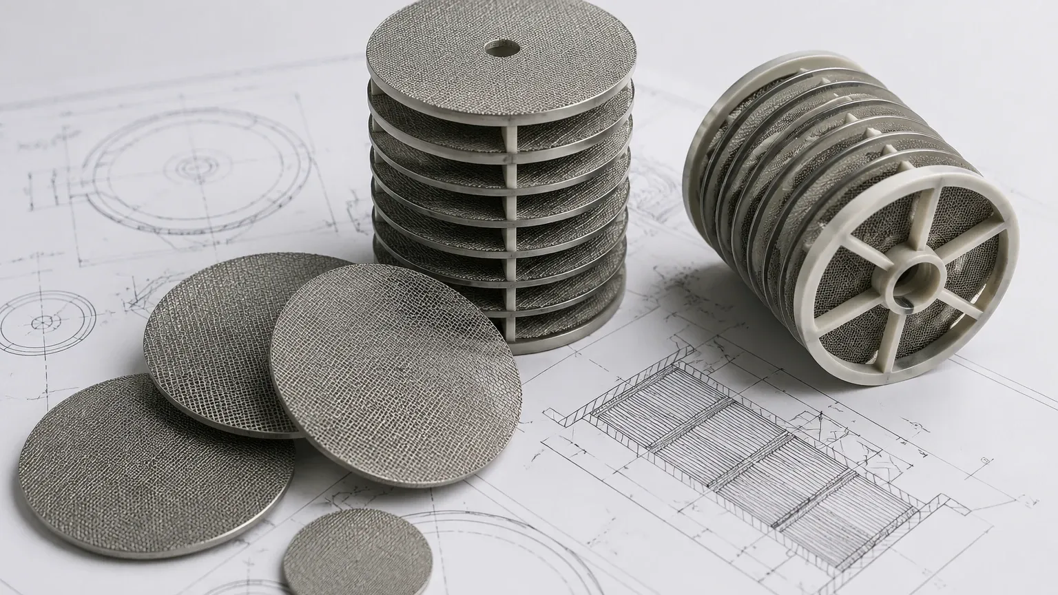
Multi-layer packs consist of several layers of mesh bonded together. The typical structure includes:
* Filtration Layer: The middle layer(s) that determine the micron rating.
* Support Layers: Coarser mesh layers on either side of the filtration media that provide structural rigidity and prevent the fine mesh from deforming under pressure.
* Drainage Layers: These facilitate the flow of the filtrate away from the filtration zone.
These layers can be joined through various methods, such as spot welding or rim binding. A comprehensive disc filter dwg will specify the number and location of spot welds to ensure the pack remains a single, cohesive unit during installation and operation.
Engineering Tolerances and Edge Treatments
The edges of a filter disc are often the most vulnerable part of the component. Without proper treatment, the cut wires of the mesh can fray, leading to contamination of the downstream fluid or injury during handling. Furthermore, the edge treatment affects how the filter seals within its housing.
Common Edge Types
1. Raw/Unbound Edges: The mesh is simply cut to size. This is common for discs that will be clamped tightly between two surfaces where fraying is not a concern.
2. Spot Welded Edges: The layers are welded together at the perimeter. This provides a low-profile finish and is often used in multi-layer packs for polymer filtration.
3. Bound Edges (Rimmed): A metal U-shaped channel (usually aluminum, stainless steel, or copper) is crimped around the edge of the disc. This provides the highest level of structural integrity and creates a reliable sealing surface for gaskets.
In a disc filter dwg, the thickness of the binding and the material used must be clearly indicated. For instance, an aluminum rim might be preferred for its malleability in sealing, while a stainless steel rim is chosen for its superior corrosion resistance in aggressive chemical environments.
Application Environments and Selection Criteria
Selecting the right Filter Discs & Packs involves more than just looking at a drawing; it requires an understanding of the operational environment. Engineers must evaluate several factors before finalizing the design specifications.
Chemical Compatibility
In the pharmaceutical and chemical industries, filters are often exposed to acids, bases, and solvents. Grade 316L stainless steel is frequently specified in the disc filter dwg because its molybdenum content provides enhanced resistance to pitting and crevice corrosion. If the drawing does not specify the exact alloy, the longevity of the filter could be severely compromised.
Temperature and Pressure
High-temperature applications, such as plastic extrusion or steam filtration, require materials that maintain their mechanical properties at elevated temperatures. The design must account for thermal expansion. If a filter disc is too tight a fit at room temperature, it may buckle or damage the housing when the system reaches operating temperature.
Filtration Accuracy (Micron Rating)
The intended particle size to be removed must align with the mesh specifications. It is important to distinguish between "nominal" and "absolute" filtration ratings in the technical documentation. Nominal refers to a percentage of particles retained, while absolute refers to the largest particle that can pass through the mesh.
Customization and OEM Capabilities
Standard off-the-shelf filters rarely meet the specific needs of specialized industrial machinery. This is why customization is a core component of the filtration industry. Manufacturers like Kaifil specialize in taking a client's disc filter dwg and translating it into a high-precision component tailored to a specific machine.
Customization options often include:
* Non-standard Shapes: While circular discs are most common, many systems require oval, rectangular, or complex geometric shapes.
* Variable Layering: Customizing the sequence of mesh layers to balance flow rate and dirt-holding capacity.
* Specialty Materials: Beyond standard stainless steel, some applications may require Monel, Inconel, or Hastelloy for extreme environments.
By working closely with an experienced manufacturer, engineering teams can refine their CAD designs to optimize the total cost of ownership. This includes designing for easier cleaning (backwashing) and longer replacement cycles, which reduces the overall maintenance burden on the facility.
Maintenance, Cleaning, and Replacement Cycles
Even the most well-designed filter disc will eventually require maintenance. The longevity of Filter Discs & Packs depends on the nature of the contaminants and the cleaning protocols in place.
Cleaning Methods
Stainless steel filters are valued for their cleanability. Common methods include:
* Ultrasonic Cleaning: Using high-frequency sound waves in a liquid bath to dislodge fine particles from the mesh pores.
* Chemical Cleaning: Using specialized solvents to dissolve organic or inorganic buildup.
* Burn-off/Pyrolysis: Used primarily in the plastics industry to remove polymer residue by heating the filter in a controlled environment.
Determining Replacement
A disc filter should be replaced when the pressure drop across the media remains high even after cleaning, or when visual inspection reveals damage to the mesh or the rim. In the disc filter dwg phase, engineers can sometimes include "wear indicators" or specific structural reinforcements that make it easier to identify when a filter has reached the end of its service life.
Conclusion: Collaborating on Technical Designs
Successful industrial filtration starts with a precise and well-communicated design. A comprehensive disc filter dwg ensures that every stakeholder—from the design engineer to the production manager—understands the requirements for material, structure, and performance. By focusing on technical accuracy and selecting the appropriate mesh configurations, businesses can achieve efficient, durable, and cost-effective filtration solutions.
When sourcing Filter Discs & Packs, it is vital to partner with a manufacturer that understands the complexities of industrial applications. Providing a detailed CAD drawing is the first step toward a high-performance filtration system that minimizes downtime and maximizes product quality. Whether your project requires a simple single-layer disc or a complex multi-layer pack with specialized rimming, technical precision remains the key to operational success.
