


Compressor Oil Separator Design
In industrial compressed air systems, particularly those utilizing oil-injected screw or vane compressors, the efficiency of the lubrication cycle is inseparable from the quality of the discharge air. The compressor oil separator is the critical component responsible for reclaiming lubricant from the compressed air stream before it exits the system. An optimized compressor oil separator design ensures that oil carryover is minimized, protecting downstream equipment from contamination while maintaining the necessary lubricant levels within the compressor’s internal circuit.
For engineers and procurement professionals, understanding the technical nuances of separator design—from media selection to flow dynamics—is essential for ensuring system longevity and operational efficiency. As a specialized manufacturer of stainless steel filtration solutions, Kaifil provides the engineering expertise required to develop high-performance separation components tailored to demanding industrial environments.
The Fundamentals of Oil Separation Mechanics
Effective compressor oil separator design relies on three primary physical mechanisms to remove oil aerosols from the air stream: direct impingement, inertial impaction, and coalescence. These mechanisms work in stages to handle varying droplet sizes, which typically range from sub-micron aerosols to larger droplets exceeding 50 microns.
Primary Separation
Before the air-oil mixture reaches the filter element, primary separation occurs through mechanical means within the separator vessel. This is often achieved through centrifugal force or a change in direction, where larger oil droplets collide with the vessel walls and fall into the sump. This stage typically removes 90% to 95% of the bulk oil.
Secondary Separation (Coalescence)
The remaining oil exists as a fine mist or aerosol. The secondary stage utilizes a coalescing filter element. As the air passes through the porous media—often composed of borosilicate glass fibers or specialized stainless steel mesh—the fine oil droplets are intercepted. Due to the high surface tension of the lubricant and the structure of the media, these droplets merge into larger beads. Once these beads reach a sufficient mass, gravity pulls them to the bottom of the filter element, where they are collected and returned to the lubrication system via a scavenge line.
Key Engineering Considerations in Compressor Oil Separator Design
Designing a separator is a balancing act between filtration efficiency and energy consumption. Engineers must evaluate several interdependent variables to achieve an optimal design.
1. Flow Velocity and Capacity
The velocity of the air passing through the separator media is a decisive factor in performance. If the velocity is too high, it can lead to "re-entrainment," where the air stream strips collected oil off the downstream side of the filter media, increasing oil carryover. Conversely, if the velocity is too low, the inertial impaction of droplets may be insufficient. Designers must calculate the effective surface area of the media to ensure that the face velocity remains within the manufacturer’s specified range for the given operating pressure.
2. Pressure Drop (Differential Pressure)
Pressure drop ($ΔP$) represents the energy cost of filtration. A high initial pressure drop forces the compressor to work harder, increasing electrical consumption. In a well-engineered compressor oil separator design, the initial saturated pressure drop is typically kept between 0.15 and 0.25 bar. As the filter accumulates contaminants over time, this pressure drop increases. Monitoring $ΔP$ is the standard method for determining when a separator element has reached the end of its service life.
3. Filtration Grade and Oil Carryover
Oil carryover is measured in parts per million (ppm) or milligrams per cubic meter (mg/m³). High-quality separators can achieve carryover levels as low as 1 to 3 ppm. Achieving these levels requires precise control over the density and layering of the filtration media. For industries like food and beverage or pharmaceuticals, where air purity is paramount, the separator design must be exceptionally robust to prevent downstream contamination.
Material Selection and Structural Integrity
The environment inside a compressor is harsh, characterized by high temperatures, rapid pressure fluctuations, and the presence of chemically active lubricants. Therefore, the materials used in the construction of the separator must be selected for durability and compatibility.
Stainless Steel and Corrosion Resistance
Stainless steel is often the material of choice for high-end or custom industrial separators. It offers superior resistance to corrosion compared to carbon steel, which is vital when moisture (condensate) is present in the air stream. Kaifil specializes in utilizing stainless steel wire mesh and precision metal components to ensure that the structural integrity of the filter is maintained even under high-pressure differentials.
End Caps and Sealing
The end caps of the separator must be securely bonded to the media to prevent bypass. In many designs, metal end caps are used for their mechanical strength. The sealing mechanism—whether it be an O-ring, a flat gasket, or a metal-to-metal seal—must be compatible with the specific type of compressor oil (synthetic, semi-synthetic, or mineral) to prevent swelling or degradation that could lead to leaks.
Evaluating Performance and Selection Criteria
When selecting or designing an oil separator for a specific application, engineers should look beyond the basic dimensions. A comprehensive evaluation includes the following criteria:
* Operational Temperature: The design must account for the maximum discharge temperature of the compressor. Standard designs are usually rated for 120°C (248°F), but specialized applications may require higher thermal resistance.
* Burst Pressure: The separator element must be able to withstand the maximum differential pressure it might encounter during a system upset without collapsing.
* Compatibility with Lubricants: Different oils have different surface tensions and viscosities. The media must be tested to ensure it can effectively coalesce the specific lubricant used in the system.
* Total Cost of Ownership (TCO): While a cheaper separator may have a lower purchase price, if it results in a higher pressure drop or shorter service life, the total cost—including energy and maintenance—will be significantly higher.
For technical teams seeking to optimize their filtration systems, reviewing professional product information and application guidance is a necessary step. You can Main Page to explore technical specifications and customized filtration solutions that align with these engineering standards.
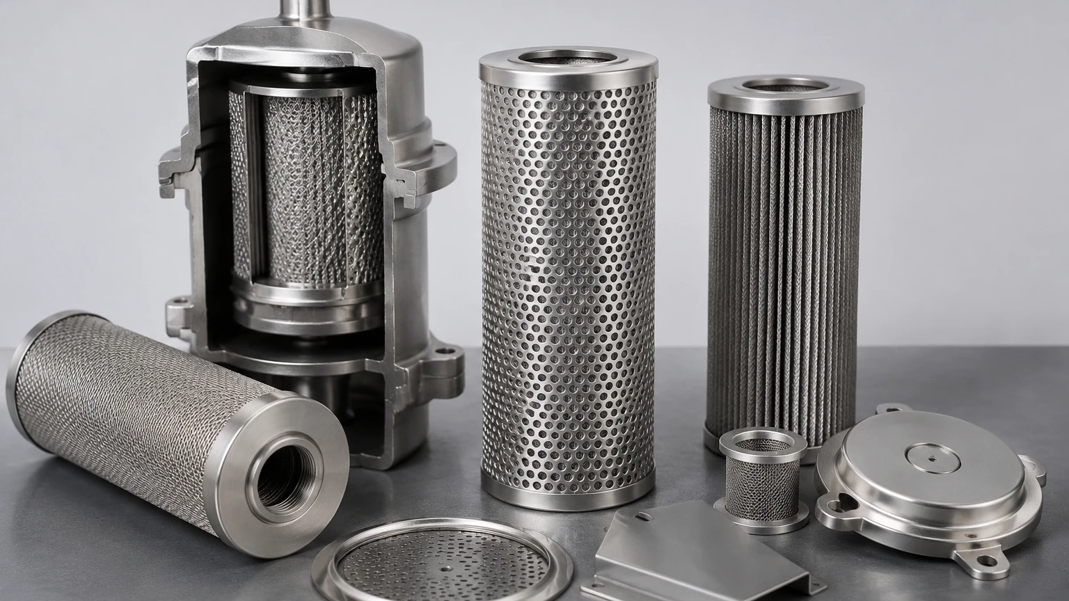
Customization and OEM Solutions
Off-the-shelf separators do not always meet the requirements of specialized industrial equipment. Custom compressor oil separator design is often necessary for unique footprints, extreme pressures, or specific flow rates.
Customization options include:
* Tailored Micron Ratings: Adjusting the media density to meet specific air quality targets.
* Bespoke Dimensions: Designing elements to fit into compact or non-standard housing configurations.
* Reinforced Structures: Adding internal support cores or external wraps to handle high-vibration environments or extreme pressure surges.
By working with a manufacturer that understands the nuances of metal filtration and precision engineering, OEMs can ensure that their compressors deliver consistent performance throughout their lifecycle.
Maintenance and Replacement Cycles
Even the best-designed separator is a consumable component. Over time, the media becomes clogged with solid particulates (dust, carbon deposits, and wear metals) that the air intake filter and oil filter failed to capture.
Indicators for Replacement
* High Differential Pressure: Most systems trigger an alarm when $ΔP$ reaches 0.8 to 1.0 bar.
* Increased Oil Consumption: If the oil level in the sump drops faster than usual, it may indicate that the separator media has been damaged or is saturated beyond its coalescing capacity.
* Oil in Downstream Lines: The presence of liquid oil in the air distribution network is a clear sign of separator failure.
Regular maintenance involves not only replacing the separator element but also inspecting the scavenge line and check valve. A blocked scavenge line will cause oil to accumulate in the "dry" side of the separator, leading to immediate oil carryover regardless of the filter's condition.
Conclusion
Precision in compressor oil separator design is a prerequisite for high-efficiency industrial air systems. By focusing on the physics of coalescence, selecting robust materials like stainless steel, and carefully calculating flow parameters, engineers can significantly reduce oil carryover and energy waste. Whether for standard industrial use or highly specialized OEM applications, the selection of the right filtration partner is vital for achieving reliable, long-term performance. For those looking to integrate these advanced filtration principles into their systems, Kaifil offers the manufacturing capability and technical support to deliver high-performance, customized solutions.
