


Data Center Liquid Cooling Rack Manifold
As high-density computing workloads—driven by artificial intelligence (AI), machine learning, and high-performance computing (HPC)—continue to push the thermal limits of traditional air cooling, liquid cooling has transitioned from a niche solution to a critical infrastructure requirement. At the heart of this transition is the data center liquid cooling rack manifold. This component serves as the primary distribution hub for coolant within the server rack, ensuring that thermal energy is efficiently captured and transported away from sensitive electronic components.
For engineers and data center architects, the rack manifold is more than a simple piping assembly. It is a precision-engineered component that must balance flow rates, manage pressure drops, and maintain material compatibility over a multi-year operational lifespan. Understanding the technical nuances of these systems, including the integration of filtration components to protect micro-channel cold plates, is essential for maintaining system uptime and cooling efficiency.
Understanding the Function of a Data Center Liquid Cooling Rack Manifold
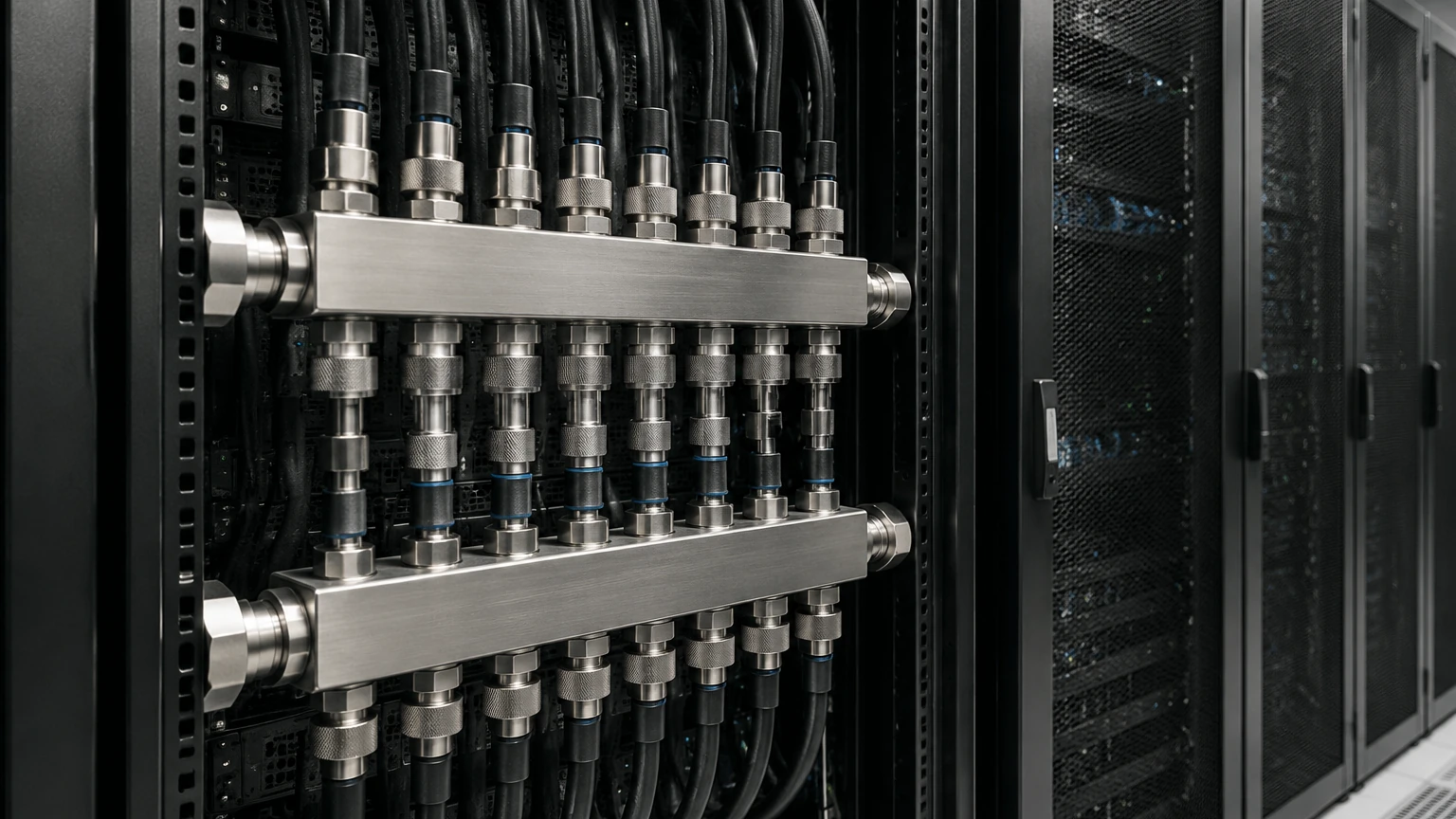
A data center liquid cooling rack manifold acts as the interface between the facility-level cooling loop and the individual server nodes. In a typical direct-to-chip (DTC) or immersive cooling setup, the manifold consists of two main vertical or horizontal rails: the supply manifold and the return manifold.
The supply manifold receives chilled coolant from the Coolant Distribution Unit (CDU) and distributes it through a series of branch lines to the cold plates or heat exchangers located within each server. Once the coolant has absorbed heat from the CPUs or GPUs, it flows into the return manifold, which collects the heated fluid and directs it back to the CDU for heat rejection.
The efficiency of this process depends heavily on the manifold’s ability to provide uniform flow distribution. Without precise engineering, servers at the top of a rack might receive less coolant than those at the bottom, leading to thermal throttling and potential hardware failure. Consequently, the design of the manifold must account for fluid dynamics and pressure balancing to ensure consistent performance across all rack units (U).
Technical Specifications and Engineering Requirements
When specifying a data center liquid cooling rack manifold, several engineering parameters must be evaluated to ensure compatibility with the broader cooling infrastructure.
Flow Rate and Pressure Drop
The manifold must be sized to handle the total volumetric flow rate required by the rack's thermal load. Engineers must calculate the pressure drop across the manifold to ensure the CDU pumps can maintain the necessary flow. Excessive internal turbulence or restrictive fittings can lead to parasitic power loss, reducing the overall Power Usage Effectiveness (PUE) of the data center.
Connection Interfaces
Manifolds typically utilize quick-disconnect (QD) couplings to allow for the hot-swapping of servers. These couplings must be "dry-break" or "non-drip" to prevent any coolant leakage during maintenance. The manifold must provide a robust mounting surface for these couplings, often incorporating flexible hoses to accommodate slight misalignments in server positioning.
Thermal Insulation
In some environments, the supply manifold may carry coolant at temperatures below the ambient dew point. To prevent condensation, which can lead to electrical shorts or corrosion, manifolds may require specialized insulation or precise control of the secondary loop temperature.
The Role of Precision Filtration in Manifold Integrity
One of the most overlooked aspects of manifold design is the integration of filtration. Modern liquid cooling systems often utilize micro-channel cold plates with internal structures measured in microns. Even microscopic debris—such as construction residues, precipitates from the coolant, or seal degradation particles—can clog these channels, leading to localized overheating.
Integrating stainless steel wire mesh filters or cartridge-based filtration units within the manifold assembly is a standard best practice. These filters act as a final line of defense. By capturing particulates before they reach the server-level cold plates, the manifold ensures the longevity of the most expensive components in the cooling loop.
For more information on high-performance filtration components used in industrial and data center applications, you can visit the Main Page to review product options and application support. High-quality filtration is not merely a maintenance item; it is a fundamental requirement for the reliability of the data center liquid cooling rack manifold.
Material Science: Why Stainless Steel Dominates Manifold Construction
Material selection is critical in liquid cooling due to the risk of galvanic corrosion and chemical degradation. Most high-end rack manifolds are constructed from stainless steel, specifically 304L or 316L grades.
Corrosion Resistance
Stainless steel provides exceptional resistance to the treated water or glycol-based coolants commonly used in data centers. Unlike copper, which can be susceptible to erosion-corrosion at high flow velocities, or aluminum, which is highly reactive in multi-metal systems, stainless steel maintains its structural integrity and does not contribute ions to the fluid that could promote galvanic activity elsewhere in the loop.
Strength and Durability
Data center environments require components that can withstand the rigors of installation and long-term operation. Stainless steel manifolds offer high tensile strength and resistance to physical impact. This durability is essential for supporting the weight of the coolant and the mechanical stress of multiple quick-disconnect cycles over the lifetime of the rack.
Cleanliness and Compatibility
Stainless steel is relatively easy to clean and passivate, ensuring that the internal surfaces of the manifold do not introduce contaminants into the cooling loop. This is particularly important in "clean-loop" specifications where fluid purity is strictly monitored to prevent the growth of biological films or the accumulation of scale.
Integration with Coolant Distribution Units (CDUs)
The rack manifold does not operate in isolation; it is a sub-component of a larger thermal management strategy. The manifold must be perfectly synchronized with the Coolant Distribution Unit (CDU). The CDU regulates the temperature, pressure, and chemistry of the coolant flowing through the manifold.
In a well-designed system, sensors located within the manifold (or at the manifold-CDU interface) provide real-time data on flow rates and temperatures. This allows the data center management system to adjust pump speeds or cooling capacity based on the actual demand of the servers. If a manifold experiences a sudden drop in pressure, it may indicate a leak or a disconnected coupling, triggering an immediate safety shutdown of the affected rack.
Maintenance Protocols and Filtration Component Replacement
While liquid cooling systems are designed for low maintenance, they are not "set and forget" systems. The rack manifold requires periodic inspection to ensure the integrity of seals and the cleanliness of internal filters.
Filter Replacement Cycles
In the initial weeks of a new data center deployment, filters within the manifold may capture a significant amount of "infant mortality" debris—particles left over from the manufacturing and installation of the piping. Engineers should monitor the pressure differential across the manifold filters. A rising pressure drop indicates that the filter is doing its job but requires cleaning or replacement. Establishing a regular replacement cycle for stainless steel filter cartridges ensures that flow is never restricted.
Leak Detection
Modern manifolds often incorporate leak detection cables or sensors along their length. Regular testing of these sensors is vital. Additionally, visual inspections of the quick-disconnect points can identify slow "weeping" leaks before they become catastrophic failures.
Selecting an OEM Partner for Custom Manifold Components
Because every data center architecture is unique—varying in rack height, power density, and coolant type—off-the-shelf manifolds often fail to meet specific engineering requirements. Working with a manufacturer that understands the complexities of fluid dynamics and precision metal fabrication is essential.
When evaluating a partner for manifold components, engineers should consider the following:
1. Customization Capabilities: Can the manufacturer adjust the spacing of ports, the diameter of the main rails, and the type of fittings to match the specific server hardware?
2. Filtration Expertise: Does the partner provide integrated filtration solutions that match the micron rating required by the cold plate manufacturers?
3. Quality Control: What testing protocols are in place? Manifolds should undergo rigorous pressure testing and helium leak testing before being deployed in a live data center environment.
4. Material Traceability: For mission-critical infrastructure, having full traceability of the stainless steel and other alloys used in construction is necessary to ensure compliance with industry standards.
Total Cost of Ownership (TCO) Considerations
While the initial investment in a high-quality stainless steel data center liquid cooling rack manifold may be higher than lower-grade alternatives, the total cost of ownership is significantly lower. A failure in the manifold can lead to the loss of an entire rack of high-value servers and hours of unplanned downtime.
By investing in a manifold designed with robust materials and integrated precision filtration, data center operators reduce the risk of component failure, minimize maintenance interventions, and ensure that the cooling system operates at peak efficiency for its entire service life. The manifold is the foundation of the liquid cooling loop; its reliability directly dictates the reliability of the data center itself.
In conclusion, the data center liquid cooling rack manifold is a sophisticated engineering solution required for the next generation of computing. By focusing on fluid dynamics, material compatibility, and the critical role of filtration, engineers can build resilient cooling infrastructures that meet the demands of modern technology. For those seeking technical guidance on the filtration components essential to these systems, consulting with experts in stainless steel filtration solutions is a recommended next step to ensure optimal performance.
