


Gas Filter Separator Configuration
In industrial gas processing, the efficiency of downstream equipment such as compressors, turbines, and meters depends heavily on the purity of the gas stream. Contaminants, whether in the form of solid particulates or liquid aerosols, can lead to mechanical wear, corrosion, and unplanned downtime. A gas filter separator is a critical engineered vessel designed to remove these impurities through a multi-stage process. Determining the correct gas filter separator configuration is a complex engineering task that requires balancing flow dynamics, filtration efficiency, and maintenance requirements.
For engineers and procurement teams, understanding the technical nuances of vessel orientation, internal stage design, and filter element selection is essential for optimizing system performance. This guide examines the fundamental engineering considerations involved in configuring gas filter separators for demanding industrial environments.
Understanding the Multi-Stage Separation Process
A standard gas filter separator configuration typically employs a two-stage or three-stage design to handle varying contaminant loads. Each stage is engineered to address specific physical properties of the impurities found in the gas stream.
Stage 1: Initial Pre-Separation
The first stage often utilizes mechanical separation techniques to remove bulk liquids and large solid particles. As the gas enters the vessel, a change in velocity or direction—often facilitated by an inlet vane or a baffle—forces heavier particles and droplets to drop out of the gas stream and into a collection sump. This stage protects the more sensitive filter elements in the subsequent stages from being overwhelmed by high liquid slugs or heavy particulate loads.
Stage 2: Coalescing and Fine Filtration
The second stage is the core of the gas filter separator. Here, the gas passes through specialized filter elements, often constructed from high-precision stainless steel wire mesh or pleated metal cartridges. These elements perform two functions: capturing fine solid particulates through mechanical entrapment and coalescing small liquid aerosols into larger droplets. As the gas flows through the porous media, the droplets collide and merge on the fibers of the filter, eventually becoming heavy enough to fall against the gas flow or be carried to the final stage for extraction.
Stage 3: Mist Extraction
The final stage involves a mist extractor, such as a wire mesh pad or a vane pack. This component ensures that any remaining liquid droplets that were re-entrained or not fully captured in the second stage are removed before the gas exits the vessel. The choice between a mesh pad and a vane pack depends on the gas velocity and the required droplet size removal efficiency.
Key Factors Influencing Gas Filter Separator Configuration
When designing or selecting a system, several variables dictate the optimal gas filter separator configuration. Engineers must evaluate these parameters to ensure the vessel operates within its intended performance envelope.
Flow Rate and Velocity Control
The volumetric flow rate of the gas is the primary driver for vessel sizing. If the internal gas velocity is too high, it can lead to "carry-over," where liquid droplets are swept through the filter media and out of the vessel. Conversely, velocities that are too low may not provide enough kinetic energy for effective mechanical separation in the first stage. Engineers use the gas density and operating pressure to calculate the actual cubic feet per minute (ACFM) and determine the necessary vessel diameter to maintain optimal velocity profiles.
Operating Pressure and Temperature
Gas filter separators must be designed to withstand specific operating pressures, often following ASME Section VIII standards. High-pressure applications require thicker vessel walls and specialized sealing mechanisms. Temperature also plays a vital role, particularly in material selection. High temperatures can affect the structural integrity of filter elements and the viscosity of liquid contaminants, which in turn impacts coalescing efficiency.
Contaminant Profile
Knowing the type and concentration of contaminants is vital. Is the gas "sour" (containing H2S)? Is there a high concentration of fine black powder (iron sulfides/oxides)? For streams with high solid loads, a configuration with larger surface area pleated elements is preferred to extend the interval between cleanings. For more information on specialized filtration components for these environments, you can Review product options and application support on our Main Page.
Vertical vs. Horizontal Vessel Orientation
The choice between a vertical and horizontal gas filter separator configuration is often dictated by floor space, the liquid-to-gas ratio, and maintenance access.
Vertical Configuration
Vertical separators are frequently used when plot space is limited. They are highly effective at handling gas streams with relatively low liquid-to-gas ratios. In a vertical vessel, gravity assists in the drainage of liquids from the coalescing elements down to the sump. However, maintenance can be more challenging as the filter elements are often located higher up, requiring platforms or specialized lifting equipment for replacement.
Horizontal Configuration
Horizontal separators are the preferred choice for applications with high liquid loads or where large volumes of solids are expected. The horizontal design provides a larger surface area for the liquid-gas interface, allowing for better gravity settling. Additionally, horizontal vessels often allow for easier access to filter elements, as they are positioned at a lower height. This configuration is common in midstream processing and large-scale industrial gas distribution.
Engineering Considerations for Filter Element Selection
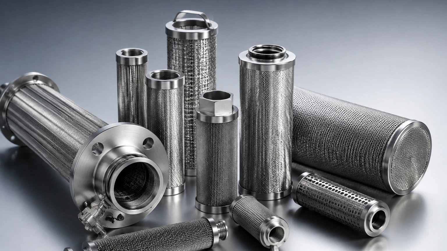
The performance of the gas filter separator configuration is ultimately limited by the quality and design of the internal filter elements. In industrial settings, stainless steel is the material of choice due to its durability and resistance to chemical attack.
1. Micron Rating and Beta Ratio: Engineers must specify the required filtration fineness. A "nominal" rating is often insufficient for critical applications; instead, an "absolute" rating or a Beta ratio (the ratio of particles upstream vs. downstream) should be used to define efficiency.
2. Pressure Drop (Delta P): Every filter element introduces a resistance to flow. The configuration must account for both the clean pressure drop and the maximum allowable dirty pressure drop. High pressure drops can lead to element collapse or bypass, compromising the entire system.
3. Structural Integrity: In high-pressure gas applications, filter elements are subject to significant mechanical stress. Stainless steel wire mesh and reinforced cartridges are used to prevent deformation under high differential pressures.
4. Cleanability and Reuse: Unlike disposable fiberglass elements, stainless steel filter components can often be cleaned and reused, providing a lower total cost of ownership over the life of the project. This is particularly advantageous in remote locations where logistics for replacement parts are difficult.
Material Selection and Corrosion Resistance
The chemical composition of the gas stream heavily influences the materials used in the gas filter separator configuration. While carbon steel may be used for the vessel shell in non-corrosive environments, the internal filtration components almost always require high-grade alloys.
* SS304: Suitable for general industrial applications where moisture is present but corrosive gases are minimal.
* SS316L: The industry standard for "sour" gas or environments containing chlorides. The low carbon content and addition of molybdenum provide superior resistance to pitting and stress corrosion cracking.
* Specialty Alloys: In extreme cases involving high concentrations of H2S or CO2 at elevated temperatures, alloys like Monel or Inconel may be necessary for the filter mesh and support structures.
Operational Maintenance and Safety
A well-configured gas filter separator must include features that facilitate safe and efficient maintenance. Without proper monitoring, a separator can become a bottleneck or a safety hazard.
Differential Pressure Monitoring
Installing differential pressure (DP) gauges across the filter stages is mandatory. A sudden rise in DP indicates element plugging, while a sudden drop could indicate a ruptured element or a seal failure. Automated systems can trigger alarms or bypass valves when DP reaches a critical threshold.
Drainage and Level Control
Liquid sumps must be equipped with reliable level control valves and sight glasses. In cold climates, heat tracing or insulation may be required to prevent collected liquids from freezing and blocking the drainage lines.
Element Replacement Protocols
The vessel configuration should include quick-opening closures (QOC) rather than standard bolted flanges if frequent element changes are anticipated. This reduces downtime and minimizes the exposure of maintenance personnel to the process gas.
Conclusion: Confirming Your Configuration
Selecting the right gas filter separator configuration is not a one-size-fits-all process. It requires a thorough analysis of the gas chemistry, flow conditions, and specific purity requirements of the downstream equipment. Engineers should confirm the following before finalizing a design:
* Validation of Flow Dynamics: Ensure the vessel diameter and nozzle sizes are adequate for the peak flow rates to prevent re-entrainment.
* Material Compatibility: Verify that all internal components, including gaskets and seals, are compatible with the gas and any injected chemicals (like methanol or corrosion inhibitors).
* Redundancy Requirements: For continuous operations, consider a duplex configuration (two 100% capacity vessels) to allow for maintenance without shutting down the process line.
By focusing on high-quality stainless steel filtration components and a robust vessel design, industrial operators can ensure long-term reliability and protection for their most critical assets. For technical specifications on custom filter elements and housing designs, engineers are encouraged to consult with specialized manufacturers who understand the rigors of industrial gas separation.
