


Gas Sparger Design
In industrial processing, the efficiency of gas-liquid mass transfer often dictates the overall productivity and cost-effectiveness of a system. Gas sparging is the process of injecting gas into a liquid through thousands of tiny pores, creating a vast number of small bubbles. This technique is fundamental in industries ranging from pharmaceutical fermentation to chemical hydrogenation and wastewater treatment. At the heart of this process is the gas sparger design, an engineering discipline that balances fluid dynamics, material science, and mechanical integrity to achieve optimal gas absorption.
For engineers and procurement teams, understanding the nuances of gas sparger design is essential for selecting components that minimize gas consumption, reduce reaction times, and withstand harsh operating environments. As a specialist in stainless steel filtration and fluid control components, Kaifil provides the technical foundation necessary to develop high-performance sparging solutions. For more information on custom manufacturing capabilities, visit the Main Page.
The Fundamentals of Mass Transfer in Sparging
The primary objective of gas sparger design is to maximize the mass transfer rate between a gas phase and a liquid phase. This is typically governed by the mass transfer equation, where the rate of transfer is proportional to the surface area available for contact.
In a sparging system, bubble size is the most critical variable. Smaller bubbles provide a significantly higher surface-area-to-volume ratio than larger bubbles. For instance, a specific volume of gas broken into 0.5 mm bubbles provides ten times more surface area than the same volume of gas released as 5 mm bubbles. Consequently, porous metal spargers, which can produce fine bubbles in the micron range, are often preferred over traditional drilled pipes or nozzles.
Effective design ensures that the gas is distributed uniformly across the vessel. If the design fails to account for liquid head pressure or gas flow velocity, "channeling" may occur, where gas escapes in a concentrated stream, bypassing large sections of the liquid and leading to inefficient processing.
Key Parameters in Gas Sparger Design
Designing an industrial-grade sparger requires a detailed analysis of several physical and operational parameters. Engineers must move beyond simple component selection to consider how the sparger interacts with the entire process system.
1. Micron Rating and Bubble Size
The pore size of the sparging element determines the initial size of the bubbles produced. Porous stainless steel elements are typically available in ratings from 0.5 to 100 microns. Choosing the correct micron rating requires a balance: finer pores create smaller bubbles (increasing mass transfer) but also result in a higher pressure drop across the element. Designers must evaluate the liquid's surface tension and viscosity, as these properties influence whether bubbles will coalesce (merge) shortly after formation.
2. Gas Flow Rate and Flux
Gas flux refers to the volume of gas passing through a unit area of the sparger surface over time. If the flux is too high, the individual bubbles emerging from the pores may merge into larger, less efficient bubbles—a phenomenon known as "jetting." Proper gas sparger design involves sizing the surface area of the porous element to maintain a "bubbling" regime, ensuring that bubbles detach from the surface before the next bubble forms.
3. Exit Velocity
The velocity at which gas exits the pores must be carefully controlled. High exit velocities can cause localized turbulence, which might be beneficial for mixing but can also lead to the mechanical degradation of sensitive biological cultures in bioreactors. In chemical reactors, excessive velocity may cause erosion of the sparger material itself if abrasive solids are present in the liquid.
4. Pressure Drop (Delta P)
Pressure drop is the difference in pressure between the inside of the sparger and the process vessel. A predictable and uniform pressure drop is necessary to ensure that gas is emitted evenly across the entire surface of the sparger. In large-scale systems, the design must account for the liquid's hydrostatic head; the pressure at the bottom of a deep tank is significantly higher than at the top, which can affect gas distribution if the sparger is not engineered correctly.
Material Selection for Industrial Spargers
Material integrity is a non-negotiable aspect of gas sparger design. Because spargers are often submerged in corrosive chemicals or subjected to high-temperature sterilization cycles, the choice of material impacts both the lifespan of the component and the purity of the final product.
* Stainless Steel 316L: The industry standard for most applications, 316L offers excellent corrosion resistance and can withstand high temperatures. It is highly suitable for food, beverage, and pharmaceutical applications due to its ability to be cleaned in place (CIP).
* Specialty Alloys: For highly aggressive environments involving concentrated acids or high-salinity fluids, materials such as Hastelloy® or Monel® may be required. These alloys provide superior resistance to pitting and stress corrosion cracking.
* Porous Metal Advantages: Unlike plastics or ceramics, porous metal spargers are mechanically robust. They can handle high differential pressures and are resistant to thermal shock, making them ideal for steam-sterilized systems.
Structural Configurations and Installation
Gas sparger design is not limited to the porous element itself; the physical configuration of the assembly must match the vessel geometry and mixing requirements.
Static Spargers
These are fixed in place, often at the bottom of a tank. Common shapes include:
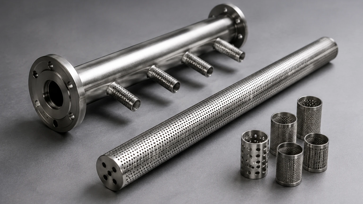
* Sparger Sticks: Single cylindrical elements used in smaller vessels or for side-entry installation.
* Sparger Rings: Circular manifolds with multiple porous elements attached, designed to provide uniform coverage across the diameter of a large tank.
* Cross-Type Manifolds: Used in rectangular or square tanks to eliminate "dead zones" where gas-liquid contact might be minimal.
In-Line Spargers
In continuous flow processes, gas is often injected directly into a pipeline. In-line gas sparger design focuses on creating a fine mist of bubbles that are immediately swept away by the flowing liquid. This is common in carbonation processes or for pH adjustment using CO2.
Dynamic or Agitated Spargers
In some designs, the sparger is located directly beneath an impeller. The mechanical shear from the impeller blades further breaks down the bubbles, enhancing mass transfer. In these cases, the sparger must be designed to withstand the turbulent forces and potential vibration caused by the agitator.
Common Risks and Engineering Challenges
Failure to account for specific process conditions during the gas sparger design phase can lead to significant operational hurdles.
* Fouling and Clogging: In liquids containing solids or biological matter, the small pores of a sparger can become restricted. Design considerations should include the ability to back-flush the system or remove the elements for ultrasonic cleaning.
* Corrosion and Contamination: If the material is not compatible with the process fluid, metal ions may leach into the product, or the sparger may suffer structural failure. Always verify the chemical compatibility of the alloy and the elastomers used in seals.
* Mechanical Stress: Spargers are often long, cantilevered structures. In agitated tanks, the fluid forces can exert significant bending moments on the sparger pipe. Support brackets and reinforced mounting flanges are critical design elements to prevent mechanical fatigue.
Applications of Optimized Gas Sparger Design
Bioprocessing and Fermentation
In the pharmaceutical industry, oxygen transfer is the limiting factor for cell growth. Precise gas sparger design ensures that dissolved oxygen levels are maintained without causing cell damage through excessive shear or foam formation.
Chemical Hydrogenation
Hydrogenation reactions require the efficient introduction of hydrogen gas into a liquid catalyst slurry. Because hydrogen is poorly soluble, the high surface area provided by porous metal spargers is essential for maintaining reaction kinetics and reducing the volume of unreacted gas that must be recycled.
Carbonation and Aeration
In the food and beverage industry, injecting CO2 or nitrogen requires precise control to achieve the desired mouthfeel and stability. Spargers must meet strict sanitary standards, ensuring there are no crevices where bacteria can proliferate.
Technical Checklist for Sparger Procurement
When collaborating with a manufacturer like Kaifil to develop a custom sparging solution, engineers should have the following data points confirmed:
1. Gas Type and Flow Rate: What is the required Standard Cubic Feet per Minute (SCFM) or Liters per Minute (LPM)?
2. Liquid Properties: What is the viscosity, density, and surface tension of the liquid?
3. Operating Environment: What are the maximum temperature and pressure? Are there corrosive agents present?
4. Vessel Dimensions: What is the height and diameter of the tank, and what is the liquid level above the sparger?
5. Connection Requirements: What are the flange sizes or thread types required for installation?
By addressing these factors, the resulting gas sparger design will be tailored to the specific needs of the application, ensuring long-term reliability and process efficiency. For a comprehensive look at the filtration and sparging components available for industrial use, visit the Main Page.
Conclusion
Gas sparger design is a sophisticated intersection of fluid mechanics and precision manufacturing. By prioritizing bubble size, material compatibility, and structural integrity, industrial facilities can achieve superior mass transfer rates and lower operational costs. Whether the application involves delicate cell cultures or aggressive chemical synthesis, the use of high-quality porous metal components remains the gold standard for efficient gas injection. Partnering with an experienced manufacturer like Kaifil ensures that every aspect of the sparger—from micron rating to manifold configuration—is engineered for performance and durability in the most demanding industrial environments.
