Inline Carbonation System
In the industrial production of beverages, mineral water, and certain chemical products, the efficient dissolution of carbon dioxide (CO2) into a liquid stream is a critical process requirement. An inline carbonation system provides a continuous, automated method for achieving precise carbonation levels without the time-consuming nature of batch processing. By injecting CO2 directly into the product flow, these systems ensure high consistency, reduced gas waste, and improved throughput. For engineers and facility managers, the performance of an inline carbonation system depends heavily on the integration of high-precision components, particularly the porous metal injectors and filtration media that facilitate gas-to-liquid mass transfer.
Understanding the Mechanics of Inline Carbonation
The fundamental principle behind an inline carbonation system is Henry’s Law, which states that the amount of dissolved gas in a liquid is proportional to its partial pressure above the liquid. To achieve rapid and stable dissolution, the system must maximize the contact surface area between the CO2 gas and the liquid medium.
Traditional batch carbonation relies on headspace pressure in a tank, which is slow and often results in uneven gas distribution. In contrast, inline systems utilize dynamic injection. As the liquid flows through a sanitary pipeline, CO2 is introduced through a specialized sparging element. This element, often a sintered stainless steel porous component, breaks the gas into millions of micro-bubbles. Because micro-bubbles have a significantly higher surface-area-to-volume ratio than larger bubbles, they dissolve almost instantaneously into the liquid stream. This process is often enhanced by a static mixer or a specialized turbulence zone downstream of the injection point to ensure complete homogenization before the product reaches the filling line or storage tank.
Key Components of an Industrial Inline Carbonation System
A robust inline carbonation system is an assembly of several high-performance modules designed to work in synchronization. Understanding these components is essential for selecting a system that meets specific production requirements.
Porous Metal Spargers and Injectors
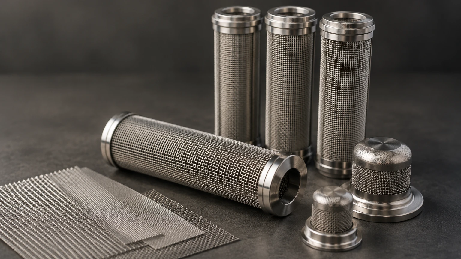
The heart of the system is the injection point. Precision-engineered sintered stainless steel spargers are preferred in industrial applications due to their ability to produce uniform bubble sizes. These components must be manufactured to exact micron ratings to ensure the gas flow is controlled and the bubbles are small enough for rapid absorption. Unlike simple drilled pipes, porous metal injectors prevent "slugging" (the formation of large gas pockets) which can cause vibration and inconsistent carbonation levels.
Flow and Pressure Control Instrumentation
To maintain a precise CO2 concentration (often measured in grams per liter or volumes of gas), the system requires accurate mass flow meters for both the liquid and the gas. Pressure sensors monitor the line pressure, ensuring it remains high enough to keep the CO2 in solution. Automated control valves adjust the gas flow in real-time based on the liquid flow rate, allowing the system to handle fluctuations in production speed without affecting product quality.
Cooling and Heat Exchange
Temperature is a primary variable in carbonation. The solubility of CO2 increases as the temperature of the liquid decreases. Many inline systems are integrated with plate heat exchangers to chill the product to the optimal carbonation temperature (typically between 0°C and 4°C). This ensures that the gas stays in solution and prevents excessive foaming during the subsequent filling process.
Engineering Considerations for Porous Metal Spargers
When designing or specifying components for an inline carbonation system, engineers must focus on the specifications of the sparging media. The choice of material and structure directly impacts the system's efficiency and the longevity of the equipment.
1. Micron Rating Selection: The pore size of the sintered metal determines the initial bubble size. While smaller pores (e.g., 0.5 to 2 microns) create finer bubbles and better dissolution, they also require higher differential pressure to overcome the "bubble point" of the media. Engineers must balance the desired carbonation speed with the available gas supply pressure.
2. Mechanical Integrity: Inline systems often operate under significant pressure and may experience hydraulic shock during pump starts or stops. Sintered stainless steel components provide the structural rigidity necessary to withstand these forces without deforming or shedding particles into the product stream.
3. Flow Distribution: The geometry of the sparger—whether it is a cylindrical probe, a ring, or a tangential injector—must be matched to the pipe diameter. The goal is to distribute the gas across the entire cross-section of the liquid flow to prevent localized saturation.
Material Selection for Food and Beverage Compliance
In the food, beverage, and pharmaceutical industries, material selection is dictated by both performance and regulatory standards. Stainless steel, specifically Grade 316L, is the industry standard for inline carbonation system components for several reasons:
* Corrosion Resistance: CO2, when dissolved in water, forms carbonic acid. While a weak acid, it can be corrosive to lower-grade metals over time. 316L stainless steel contains molybdenum, which provides superior resistance to acidic environments and pitting.
* Surface Finish: Components must be manufactured with a high degree of smoothness (measured in Ra). A low Ra finish prevents microbial attachment and ensures that the system can be effectively sanitized. For many applications, electro-polishing is required to achieve the necessary sanitary standards.
* Thermal Stability: Carbonation systems often undergo Clean-In-Place (CIP) or Steam-In-Place (SIP) cycles. The materials must be able to withstand rapid temperature shifts from near-freezing production temperatures to high-temperature cleaning solutions without losing structural integrity.
Optimizing Carbonation Performance and Efficiency
To achieve the highest efficiency in an inline carbonation system, several operational parameters must be optimized. Simply increasing gas pressure is rarely the most effective solution and can lead to wasted CO2 and unstable products.
Pressure Management: The system pressure downstream of the injector must be maintained above the equilibrium pressure of the desired carbonation level. If the pressure drops too low, the CO2 will break out of the solution, leading to "breakout" or foaming. This is often managed using a backpressure valve at the end of the carbonation loop.
Gas-to-Liquid Ratio: Precise calibration of the mass flow controllers ensures that the exact amount of CO2 is injected. Advanced systems use CO2 analyzers (using infrared or thermal conductivity sensors) to provide a feedback loop to the controller, allowing for automatic adjustments if the incoming product temperature or flow rate changes.
Residence Time: While micro-bubbles dissolve quickly, providing a short "holding tube" or residence time after the injection point allows the gas to fully stabilize within the liquid. This reduces the risk of gas pockets reaching the filler, which can cause inconsistent fill levels and bottle bursts.
Maintenance, Sanitation, and Service Life
Like any precision industrial equipment, an inline carbonation system requires a structured maintenance program. The most common challenge is the fouling of the porous sparging media. Depending on the product being carbonated (e.g., high-sugar soft drinks or pulpy juices), organic residues can accumulate within the pores of the sintered metal.
* CIP Procedures: Regular CIP cycles using caustic and acidic cleaners are usually sufficient to maintain the system. However, the porous media requires specific attention. Back-flushing the sparger with cleaning solution or treated water can help dislodge particles trapped on the surface.
* Inspection Cycles: Engineers should regularly monitor the differential pressure across the sparger. A steady increase in the pressure required to maintain gas flow is a clear indicator of pore clogging.
* Replacement Strategy: While sintered stainless steel is highly durable, it is not infinite. Over years of use and aggressive cleaning, the pore structure may eventually degrade. Establishing a replacement cycle based on performance data ensures that carbonation quality does not drift over time.
Sourcing Customized Filtration and Carbonation Components
For many manufacturers, a standard off-the-shelf solution may not meet the specific constraints of their production line. Customization is often required in terms of fitting types (e.g., Tri-clamp, NPT, or Flanged), probe lengths, and specific micron ratings for unique liquid viscosities.
Working with an experienced manufacturer of stainless steel filtration and sparging components allows engineering teams to develop solutions tailored to their specific flow rates and carbonation targets. Professional manufacturers provide the technical expertise needed to select the correct porosity and surface area to ensure maximum gas absorption with minimal pressure drop. For those looking to optimize their filtration or gas injection processes, you can Review product options and application support to find components that align with industrial standards and specific application needs.
By focusing on high-quality materials and precision engineering, companies can ensure their inline carbonation system operates with high reliability. Whether the application is in the craft brewery sector, large-scale soft drink production, or industrial water treatment, the integration of superior porous metal components is the key to achieving consistent, high-quality carbonation results. From the initial material selection to the final integration into the production line, every detail in the design of these components contributes to the overall efficiency and total cost of ownership of the system.