


Expanded Metal 3d Model
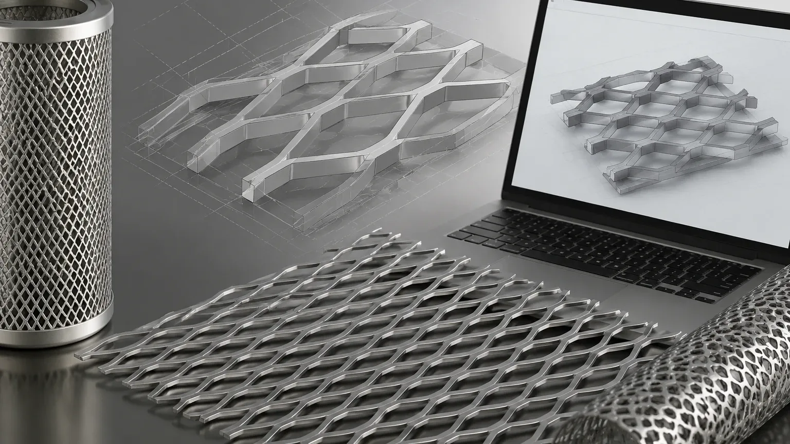
In modern industrial design and engineering, the transition from two-dimensional schematics to high-fidelity three-dimensional representations has become standard practice. For engineers specializing in filtration, structural support, and fluid dynamics, the use of an expanded metal 3d model is essential for verifying fitment, calculating flow resistance, and ensuring structural integrity before a single sheet of material is cut. As a professional manufacturer, Kaifil understands that providing accurate technical data for Perforated & Expanded Metal is critical to the success of complex industrial projects.
This guide explores the technical nuances of expanded metal geometry, the considerations for integrating these models into CAD environments, and how material selection influences the performance of the final filtration component.
Understanding the Geometry of Expanded Metal
Unlike perforated metal, which is created by punching holes and removing material, expanded metal is manufactured by simultaneously slitting and stretching a solid sheet. This process creates a diamond-shaped pattern without any material waste. To create a functional expanded metal 3d model, one must understand the four primary geometric variables that define the mesh:
1. LWD (Long Way of Diamond): The distance from the center of one joint to the center of the next joint across the long axis of the diamond.
2. SWD (Short Way of Diamond): The distance from the center of one joint to the center of the next joint across the short axis.
3. Strand Width: The amount of metal between the openings, which determines the overall strength and weight.
4. Strand Thickness: The thickness of the original base material.
In a 3D environment, these dimensions are further complicated by the orientation of the strands. Standard (raised) expanded metal features strands that are tilted at an angle to the plane of the sheet. This creates a three-dimensional profile that provides excellent grip and directional flow characteristics but requires more complex modeling than flattened expanded metal, where the mesh is passed through a cold-rolling mill to create a smooth, level surface.
The Role of 3D Modeling in Industrial Filtration
For Kaifil’s core business—custom stainless steel filtration solutions—the 3D model serves as the blueprint for precision. When designing a stainless steel filter cartridge, expanded metal is often utilized as a support core or an outer protective wrap.
Fitment and Tolerance Verification
Using an expanded metal 3d model allows engineers to simulate how the mesh will interact with other components, such as end caps, internal support tubes, and pleated filter media. Because expanded metal has a specific "thickness" that exceeds the original gauge of the sheet (in its raised form), 3D modeling prevents interference issues during the assembly of multi-layered filtration systems.
Flow Dynamics and Pressure Drop
In chemical processing and hydraulic applications, the angle of the strands in expanded metal significantly impacts fluid flow. A 3D model enables Computational Fluid Dynamics (CFD) analysis to predict pressure drops across the filter. Engineers can determine if the "open area" provided by a specific LWD/SWD configuration meets the flow requirements of the system without compromising the structural support needed for the filter media.
Key Technical Specifications for CAD Integration
When importing or creating an expanded metal 3d model, technical professionals must account for several physical properties that affect the simulation and the final procurement process. At Kaifil, we emphasize the following parameters for industrial-grade applications:
Material Selection (304 vs. 316L Stainless Steel)
The choice of material is the first boundary in the design process. For pharmaceutical and food and beverage applications, 316L stainless steel is preferred due to its superior corrosion resistance and ability to withstand rigorous cleaning cycles. The 3D model should reflect the density and mechanical properties of the chosen alloy to ensure accurate weight calculations and stress analysis.
Open Area Calculations
The percentage of open area determines the efficiency of the filtration process. For expanded metal, this is calculated based on the relationship between the strand width and the SWD. In a 3D CAD environment, the software can automatically calculate the projected open area, which is vital for engineers balancing the need for high flow rates with the requirement for mechanical rigidity.
Surface Finish and Treatment
In many B2B applications, the surface finish is not merely aesthetic. For water treatment or chemical processing, an expanded metal model might need to account for electrolytic polishing or passivation. These treatments ensure that the mesh does not introduce contaminants into the process stream and that the surface is smooth enough to prevent bacterial growth.
Modeling Challenges: Computational Load vs. Geometric Accuracy
One of the most common issues engineers face when working with an expanded metal 3d model is the high computational cost of rendering complex mesh patterns. A single sheet of expanded metal contains hundreds or thousands of individual facets. If a project involves large-scale industrial equipment, such as a massive water treatment intake screen, modeling every strand as physical geometry can slow down CAD software.
Texture Mapping vs. Physical Geometry
For many preliminary designs, engineers use "texture mapping" or "appearance filters" to represent the mesh. This provides a visual guide without the processing overhead. However, for the final stages of design—specifically for parts produced by Kaifil—physical geometry is required. This ensures that the laser cutting or welding paths are accurately defined and that the structural integrity of the filter cartridge is verified under simulated pressure loads.
Simplifying the Pattern
To optimize performance, many engineering teams model a small "representative volume element" (RVE) of the expanded metal in high detail and then use pattern features in software like SolidWorks or Autodesk Inventor to populate the larger area. This approach maintains accuracy at the joints and strands while managing the software's memory usage.
Selecting the Right Perforated & Expanded Metal for Your Project
Choosing between perforated and expanded metal often depends on the specific demands of the industrial environment. While both provide filtration and support, their physical characteristics differ significantly in a 3D space.
* Perforated Metal: Offers precise hole sizes and shapes (round, square, hexagonal). It is generally easier to model and provides a flat surface that is ideal for fine-mesh support.
* Expanded Metal: Provides a higher strength-to-weight ratio and a unique 3D structure that can deflect or direct flow. It is often more cost-effective because the manufacturing process involves no material scrap.
When evaluating Perforated & Expanded Metal for a project, engineers should confirm the maximum pressure the mesh will encounter, the particle size to be retained, and the chemical environment. Kaifil’s engineering team works closely with global customers to translate these requirements into a manufacturable design, often starting with the client’s 3D model to ensure seamless integration into their existing systems.
Customization and OEM Capabilities at Kaifil
As a specialist in custom stainless steel filtration, Kaifil does not just provide standard sheets. Our value lies in our ability to customize the mesh to meet specific engineering tolerances. Whether you require a specific strand angle to optimize flow or a custom LWD/SWD ratio for a proprietary filtration system, our manufacturing capabilities are designed to meet these needs.
Engineering Support for Custom Designs
Before moving to production, we encourage purchasing teams and engineers to share their 3D models. This allows us to:
* Suggest optimizations for material usage.
* Identify potential stress points in the mesh joints.
* Ensure that the selected stainless steel grade is appropriate for the intended temperature and pressure ranges.
* Verify that the filtration accuracy (micron rating) aligns with the geometric openings of the expanded metal.
Conclusion: The Path to Precision Filtration
An expanded metal 3d model is more than just a visual aid; it is a critical tool for risk mitigation in industrial engineering. By accurately representing the complex geometry of the mesh, engineers can ensure that their filtration systems perform reliably in demanding environments, from pharmaceutical cleanrooms to heavy-duty hydraulic systems.
At Kaifil, we combine our manufacturing expertise with a deep understanding of engineering requirements to deliver high-performance filtration components. By focusing on quality, durability, and precise filtration performance, we help our partners achieve efficient and cost-effective results. When your project demands the structural integrity and versatility of expanded or perforated metal, selecting a partner who understands the technical depth of your 3D designs is the first step toward a successful installation.
