


Expanded Metal Appearance Solidworks
In industrial engineering and the design of filtration systems, the ability to accurately represent materials in CAD environments like SolidWorks is essential for both aesthetic visualization and functional assembly planning. When designing components such as filter cages, protective screens, or support structures, engineers frequently utilize expanded metal. However, modeling the intricate geometry of expanded metal—with its thousands of interconnected diamonds and strands—can significantly degrade software performance.
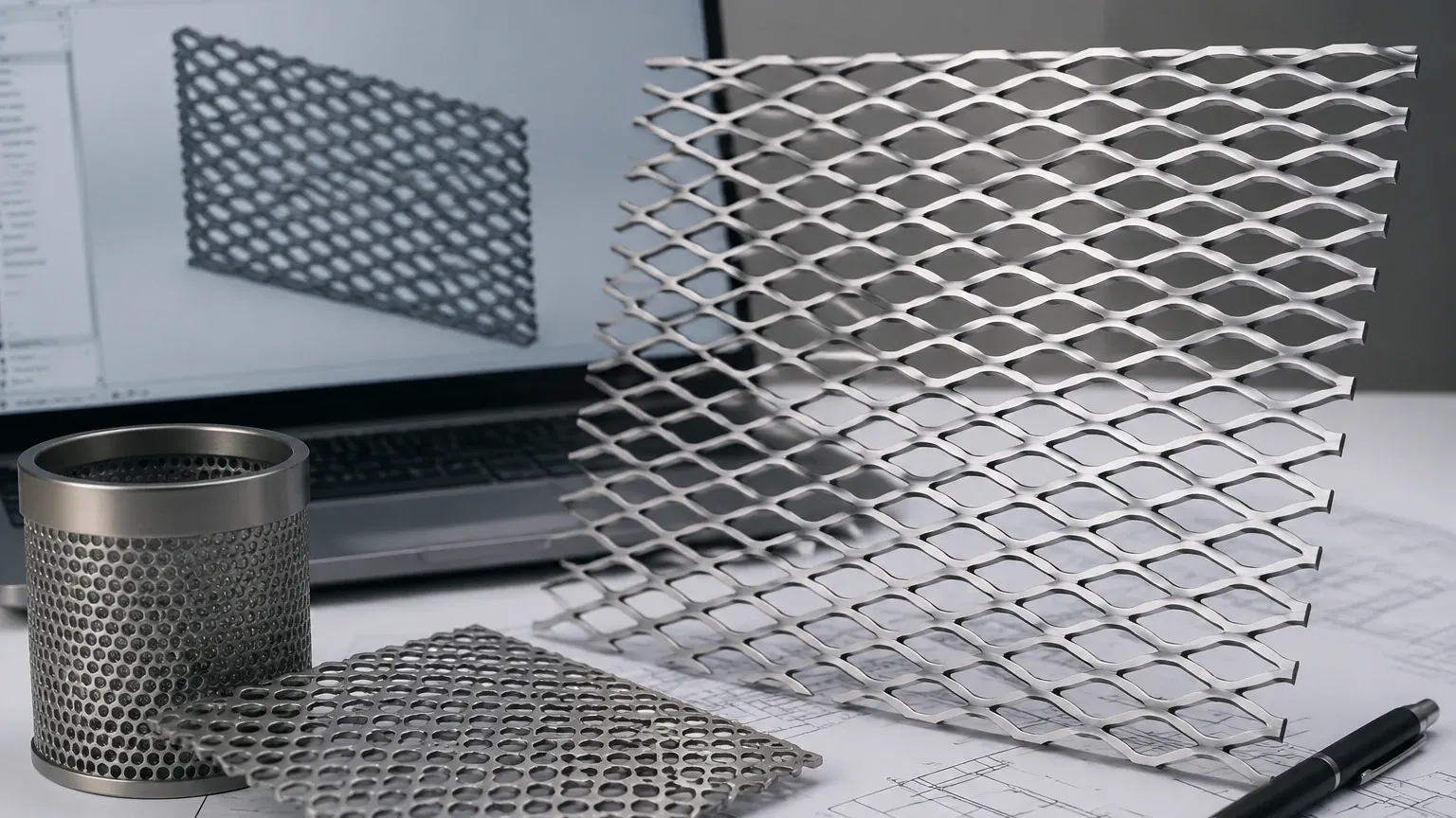
Achieving a realistic expanded metal appearance SolidWorks users can rely on involves a strategic balance between visual accuracy and computational efficiency. This guide explores the technical methods for applying these appearances, the engineering considerations behind expanded metal selection, and how these digital representations translate into physical Perforated & Expanded Metal components used in demanding industrial environments.
The Importance of Appearance Over Geometry in CAD
For many mechanical engineers, the initial instinct is to model every feature of a part. While this is feasible for simple perforated plates with a few dozen holes, it becomes a massive technical hurdle when dealing with expanded metal. Expanded metal is created by simultaneously slitting and stretching a solid sheet, resulting in a continuous mesh of diamond-shaped openings.
If an engineer were to use the "Cut-Extrude" and "Pattern" features in SolidWorks to create a physical mesh on a large cylindrical filter cartridge, the resulting file would contain thousands of faces and edges. This leads to:
1. Increased Rebuild Times: Every time a change is made to the assembly, SolidWorks must recalculate the geometry of every diamond.
2. Graphics Lag: Rotating or zooming in on the model becomes sluggish as the GPU struggles to render the complex mesh.
3. File Size Inflation: Large files are harder to share, back up, and manage within PDM (Product Data Management) systems.
By using an "Appearance" or a "Texture" with an alpha channel (transparency), engineers can simulate the look and open area of the mesh without the geometric overhead. This allows for smooth assembly manipulation while providing enough visual data for design reviews and client presentations.
How to Apply Expanded Metal Appearance in SolidWorks
To create a functional representation of expanded metal, SolidWorks utilizes a combination of textures and mapping techniques. Here is the technical workflow for applying these appearances effectively:
1. Utilizing the Appearances Library
SolidWorks includes a default library of textures. To find mesh-like structures, navigate to the Task Pane > Appearances, Scenes, and Decals. Under the Miscellaneous or Metal folders, you will often find "Mesh" or "Grate" options. While these may not perfectly match specific industrial expanded metal specifications, they serve as a baseline.
2. Customizing the Texture Map
Industrial filtration often requires specific diamond dimensions, such as the Long Way of Diamond (LWD) and Short Way of Diamond (SWD). To match your CAD model to a physical product from Kaifil, you must edit the appearance:
* Mapping Tab: Adjust the scale of the texture. If your LWD is 10mm, you must ensure the texture scale matches the physical dimensions of your part in the model.
* Surface Finish: For stainless steel filtration components, ensure the reflectivity and specular highlights match a 304 or 316 stainless steel finish (e.g., dull, 2B, or polished).
3. Implementing Transparency (Alpha Channels)
To make the "holes" in the expanded metal appear transparent in your model, the appearance must use a PNG or TIFF file with an alpha channel. In the SolidWorks Appearance PropertyManager, you can define the "Illumination" properties to recognize these transparent areas. This is critical for checking internal clearances within a filter housing or ensuring that internal components are visible through the mesh.
Engineering Specifications for Expanded Metal
When moving from a expanded metal appearance SolidWorks model to a procurement phase, engineers must define the physical characteristics of the mesh. Unlike perforated metal, which is defined by hole diameter and pitch, expanded metal is defined by the following parameters:
* SWD (Short Way of Diamond): The distance from the middle of the bond on one side to the middle of the bond on the opposite side, measured across the short axis.
* LWD (Long Way of Diamond): The distance measured across the long axis of the diamond.
* Strand Width: The amount of metal fed into the precision dies to create the mesh.
* Strand Thickness: The thickness of the original base metal.
* Open Area Percentage: This is the most critical factor for filtration. It determines the flow rate and pressure drop across the filter.
At Kaifil, we provide precision-manufactured expanded metal that adheres to these strict tolerances, ensuring that the performance of the physical component matches the calculations performed during the design phase.
Material Selection for Industrial Filtration
While a CAD appearance can simulate any material, the physical environment of the application dictates the actual material choice. In industrial B2B sectors, the following materials are standard:
| Material | Application Environment | Key Benefit |
| :— | :— | :— |
| 304 Stainless Steel | General industrial, food processing | Cost-effective corrosion resistance |
| 316L Stainless Steel | Chemical, pharmaceutical, marine | High resistance to pitting and chlorides |
| Carbon Steel | Hydraulic oils, non-corrosive fluids | High structural strength at lower cost |
| Specialty Alloys | High-temperature aerospace, acidic processing | Extreme temperature and chemical stability |
For filtration applications, 316L stainless steel is often the preferred choice due to its superior weldability and resistance to the aggressive cleaning agents used in CIP (Clean-in-Place) cycles.
Transitioning from CAD to Manufacturing
Once the design is finalized in SolidWorks using the appropriate appearance, the next step is providing the manufacturer with accurate technical drawings. It is important to note that because the mesh was modeled as an "appearance," the 2D drawing will not automatically show the diamond pattern unless specifically configured.
Engineers should include a detailed callout on the drawing specifying the expanded metal type (e.g., "Standard" vs. "Flattened").
* Standard Expanded Metal: The strands and bonds are set at a uniform angle to the plane of the sheet. This provides extra strength and rigidity but results in a thicker profile.
* Flattened Expanded Metal: The mesh is passed through a cold-rolling reducing mill, resulting in a smooth, flat surface. This is often preferred for outer guards where a flush surface is required to prevent snagging or to facilitate easier cleaning.
Why Precision Matters in Filtration Support
In many filter cartridge designs, expanded metal serves as the outer or inner support core. If the mesh is not manufactured with precision, several risks arise:
1. Structural Collapse: If the strand width or thickness is under-specified, the filter may fail under high differential pressure.
2. Media Damage: Sharp edges or burrs on the expanded metal can puncture the delicate wire mesh or non-woven filter media it is meant to protect.
3. Flow Inconsistency: Variations in the SWD and LWD can lead to uneven flow distribution, causing localized clogging and shortening the filter's service life.
Kaifil’s manufacturing process focuses on eliminating these risks through rigorous quality control and advanced slitting and stretching technology. By working closely with engineering teams during the design phase, we ensure that the Perforated & Expanded Metal components integrated into your systems provide maximum durability.
Conclusion: Bridging the Digital and Physical Gap
Using an expanded metal appearance SolidWorks workflow allows engineers to maintain high-performance CAD assemblies while providing a realistic preview of the final product. However, the visual representation is only the first step. The success of an industrial filtration project depends on the accurate translation of those digital specs into a high-quality physical component.
When specifying expanded metal for your next project, consider the total cost of ownership, including the lifespan of the material in its operating environment and the ease of maintenance. Kaifil provides the technical expertise and manufacturing capabilities to produce custom stainless steel filtration solutions that meet your exact requirements, from precision metal filter components to robust support structures.
For engineers and purchasing teams looking to optimize their filtration systems, selecting a partner who understands both the CAD design constraints and the realities of metal fabrication is essential. Contact Kaifil today to discuss your specific application needs and ensure your designs are supported by world-class filtration components.
