


Expanded Metal in Solidworks
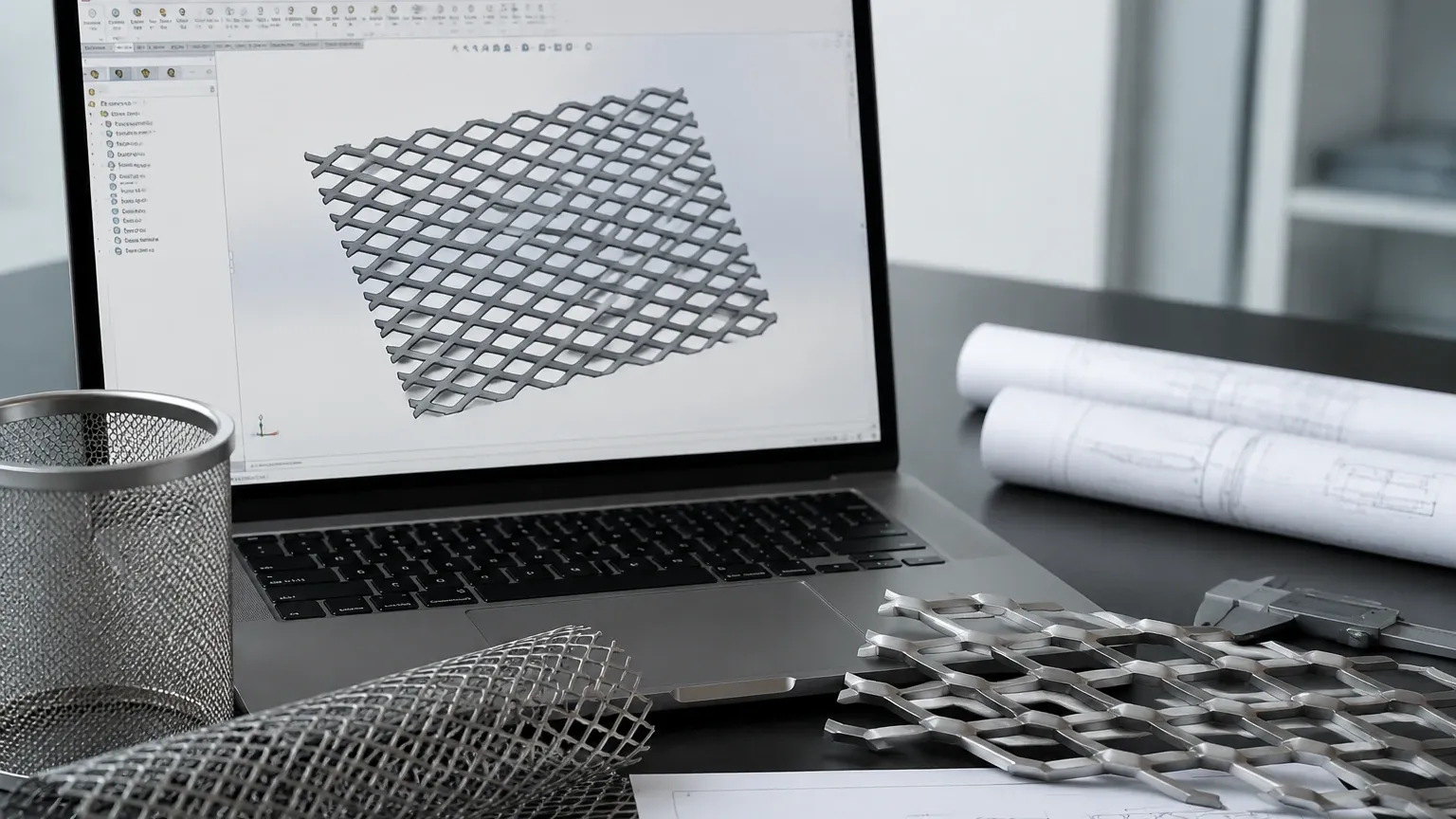
In industrial design and filtration engineering, the integration of specialized materials into 3D CAD environments is essential for accurate prototyping and performance simulation. For engineers designing filtration housings, support structures, or protective screens, modeling expanded metal in Solidworks presents a unique set of challenges. Unlike standard sheet metal, expanded metal features a complex, three-dimensional geometry created by simultaneously slitting and stretching the material. This article explores the technical methodologies for representing expanded metal in CAD, the engineering considerations for its application in industrial filtration, and how these digital designs translate into high-performance components manufactured by Kaifil.
The Role of Expanded Metal in Industrial Filtration Systems
Expanded metal is a versatile material widely used in the filtration industry as a support medium for finer wire mesh or as a primary coarse filter. Its manufacturing process involves no material waste, as the metal is stretched rather than punched, making it a cost-effective alternative to perforated sheets in many applications.
From an engineering perspective, the structural integrity of a filter cartridge often depends on the rigid skeleton provided by Perforated & Expanded Metal. When designing these components in Solidworks, the engineer must account for the material's open area, flow resistance, and mechanical strength. Expanded metal provides a high strength-to-weight ratio and a unique "directional" flow characteristic due to the angle of the strands, which can be leveraged to influence fluid dynamics within a pressurized system.
Strategic Modeling of Expanded Metal in Solidworks
When addressing the requirement for expanded metal in Solidworks, engineers typically choose between two primary modeling strategies: visual representation (textures) and geometric modeling (features). The choice depends heavily on the intended use of the CAD model, such as whether it is for a high-level assembly, a detailed FEA (Finite Element Analysis) study, or a manufacturing drawing.
1. Appearance and Texture Mapping
For large-scale industrial assemblies, such as a chemical processing plant layout where multiple filter housings are present, modeling every individual strand of expanded metal is computationally prohibitive. In these cases, the most efficient method is to use a "RealView" appearance or a custom texture with an alpha channel (transparency). This allows the engineer to visualize the expanded metal and calculate the mass properties based on an equivalent density, without taxing the system’s GPU and CPU with thousands of small faces.
2. Feature-Driven Patterns
For components where the exact geometry is critical—such as a custom filter support core—engineers must model the actual geometry. This is typically achieved by creating a single "diamond" unit cell using a combination of 3D sketches and swept bosses, and then utilizing the "Fill Pattern" or "Linear Pattern" tool. While this provides a high level of detail, it significantly increases the rebuild time of the part. To mitigate this, Solidworks users often use "Simplified Configurations" to suppress these complex patterns when working in larger assemblies.
Engineering Parameters: LWD, SWD, and Strand Width
To accurately model expanded metal, it is necessary to understand the industry-standard terminology that defines its geometry. These parameters are essential when setting up equations or global variables in Solidworks to ensure the digital model matches the physical product supplied by Kaifil.
* LWD (Long Way of Diamond): The distance from the center of one joint to the center of the next joint across the long axis.
* SWD (Short Way of Diamond): The distance from the center of one joint to the center of the next joint across the short axis.
* Strand Width: The amount of metal fed into the expanding machine between slits.
* Strand Thickness: The thickness of the original base metal.
* Open Area: The percentage of the total area that is not obstructed by metal. This is a critical calculation for filtration efficiency and pressure drop analysis.
In Solidworks, these dimensions can be linked to a design table, allowing engineers to quickly swap between different expanded metal specifications (e.g., standard vs. flattened) to see how they impact the overall design of the filtration component.
Performance vs. Detail: Managing Large Assemblies
A common pitfall when working with expanded metal in Solidworks is the impact on assembly performance. A single sheet of expanded metal can contain thousands of edges. If an engineer patterns this geometry across several filter cartridges in a large housing, the assembly may become unresponsive.
To manage this, technical professionals often employ the following techniques:
* Envelope Components: Using a simplified cylinder or sheet to represent the expanded metal in the main assembly.
* Decals: Applying a graphic representation of the mesh that does not contain actual geometry but provides the necessary visual cues for orientation and placement.
* Split Parts: Modeling the expanded metal as a separate part and using "Large Assembly Mode" to limit the graphical overhead.
By balancing detail with performance, engineers can maintain an efficient workflow while still ensuring that the critical dimensions for fit and function are preserved.
Transitioning from CAD to Manufacturing with Kaifil
Once the design of the expanded metal component is finalized in Solidworks, the transition to physical manufacturing requires a partner with deep expertise in metal fabrication. Kaifil specializes in translating complex engineering requirements into high-quality stainless steel filtration solutions.
When a customer provides a CAD model or a technical specification, Kaifil’s engineering team evaluates the manufacturability of the design. This includes assessing the material choice—typically 304 or 316L stainless steel for industrial applications—and ensuring that the chosen expansion pattern provides the necessary structural support for the filtration media. Our advanced manufacturing capabilities allow for the production of custom expanded metal cylinders, flat panels, and reinforced structures that meet the exact tolerances specified in the digital model.
Comparing Perforated & Expanded Metal for Filter Support
In many industrial B2B applications, engineers must decide between using perforated metal or expanded metal for filter internal supports. Each has distinct advantages that should be reflected in the CAD design:
* Perforated Metal: Offers precise hole sizing and spacing, which is ideal for applications requiring very specific flow patterns or high pressure resistance. It is easier to model in Solidworks using a simple hole pattern.
* Expanded Metal: Generally more cost-effective and provides a higher open area percentage for the same material weight. The three-dimensional nature of the strands can also act as a pre-filter, capturing larger debris before it reaches the primary mesh layer.
Kaifil provides both solutions, allowing purchasing teams and engineers to select the material that best fits their total cost and performance objectives. Whether the application involves hydraulic fluids, food and beverage processing, or pharmaceutical filtration, selecting the right base structure is paramount to the longevity of the filter.
Material Selection and Corrosion Resistance
In the chemical and pharmaceutical industries, the environmental conditions are often harsh. When modeling expanded metal in Solidworks, the material properties assigned to the part (such as density and yield strength) must reflect the actual alloy used.
Stainless steel is the preferred material for Kaifil’s filtration components due to its exceptional corrosion resistance and durability. 316L stainless steel, in particular, is used for its resistance to pitting and crevice corrosion in chloride-rich environments. For engineers, ensuring that the CAD metadata correctly identifies these alloys is crucial for procurement accuracy and lifecycle management. A well-defined CAD model helps in calculating the total weight of the system, which is vital for shipping, installation, and structural support calculations.
Maintenance and Durability Considerations
Industrial filters are subject to rigorous cleaning cycles, including backwashing and chemical CIP (Clean-In-Place) processes. The expanded metal support must withstand these stresses without deforming. When designing in Solidworks, engineers can use Simulation modules to test the structural integrity of the expanded metal under various pressure loads.
Key evaluation criteria for the durability of expanded metal include:
* Joint Integrity: The strength of the "bonds" where the strands intersect.
* Edge Treatment: Whether the edges are left "random" or are finished with a solid border to prevent fraying and facilitate easier installation.
* Flattening: Whether the expanded metal is "standard" (raised) or "flattened" (rolled to a smooth surface). Flattened expanded metal is often preferred in filtration to prevent damage to the delicate wire mesh layers it supports.
Conclusion: Optimizing the Engineering Workflow
Modeling expanded metal in Solidworks is more than a visual task; it is a critical step in the engineering of efficient industrial filtration systems. By understanding the geometric parameters of LWD and SWD, and by choosing the appropriate modeling strategy to balance detail with system performance, engineers can create accurate designs that are ready for production.
Kaifil supports this process by providing the technical expertise and manufacturing precision needed to turn these digital designs into reality. From custom OEM components to standard filtration supports, our focus on quality and durability ensures that your filtration systems perform reliably in the most demanding environments. When your project requires the specific performance characteristics of Perforated & Expanded Metal, partnering with a manufacturer that understands both the CAD design constraints and the physical manufacturing realities is the key to a successful implementation.
