


Perforated Metal Facade Detail Drawings
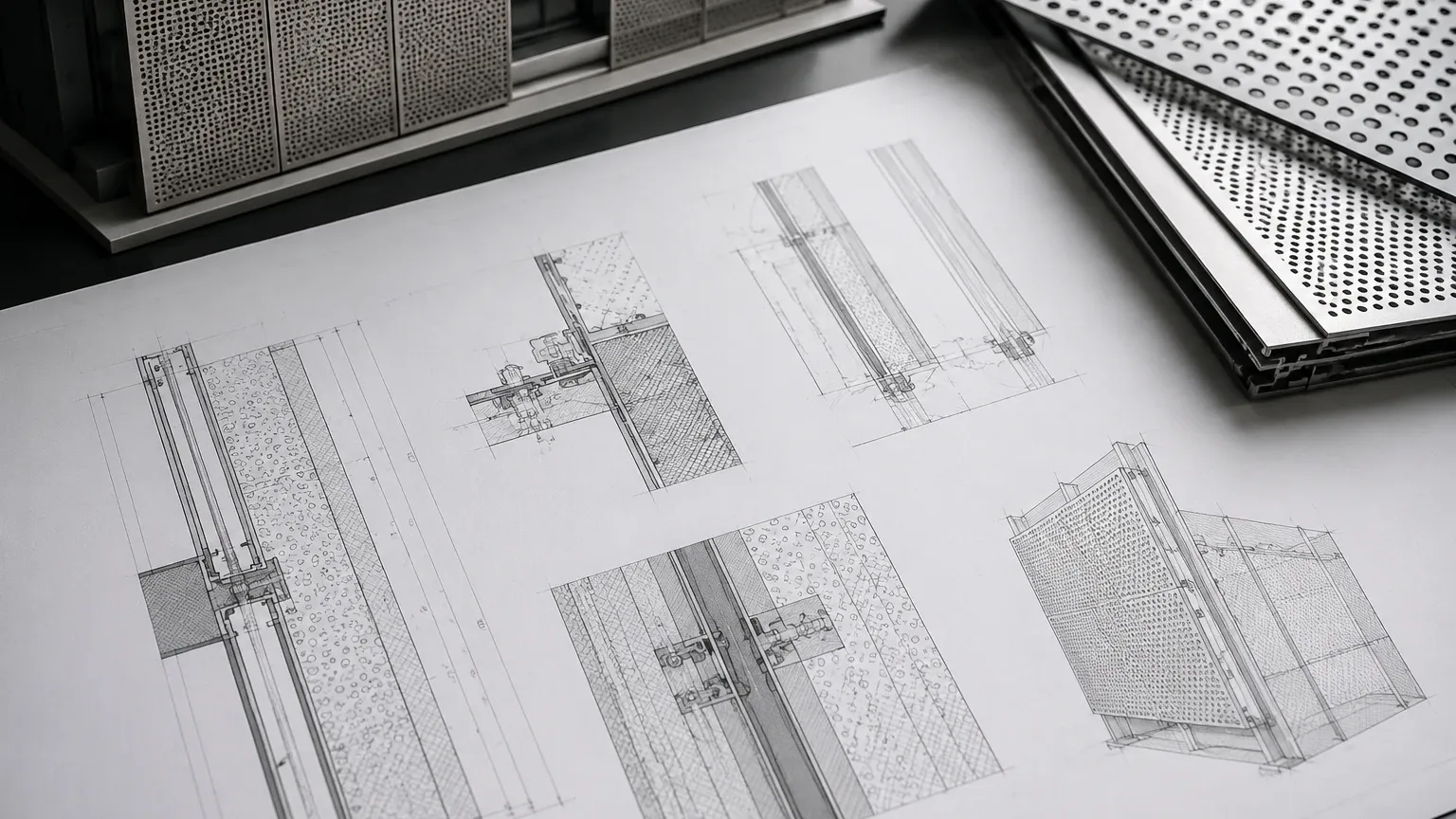
In the transition from architectural concept to physical reality, the accuracy of perforated metal facade detail drawings serves as the primary safeguard for structural integrity and aesthetic consistency. For engineers and procurement professionals, these drawings are not merely visual representations; they are technical documents that dictate material performance, installation efficiency, and long-term durability. When sourcing Perforated & Expanded Metal, understanding the nuances of these detail drawings is essential to ensure that the manufactured components align with the specific environmental and mechanical requirements of the project.
Perforated metal facades provide a unique combination of solar shading, natural ventilation, and acoustic control. However, achieving these functional benefits requires a rigorous approach to detailing. This article examines the critical elements of facade detail drawings, the engineering considerations behind material selection, and the technical specifications required to bridge the gap between design and manufacturing.
The Role of Perforated & Expanded Metal in Modern Facades
Modern industrial and commercial architecture increasingly utilizes perforated and expanded metal due to its versatility and strength-to-weight ratio. While both materials are used for cladding, their manufacturing processes and resulting physical properties differ significantly, which must be reflected in the detail drawings.
Perforated metal is produced by punching a series of holes into a solid sheet. This process allows for high precision in hole size, shape (round, square, slotted, or decorative), and spacing. It is often the preferred choice when specific open area percentages are required for airflow or light transmission. In contrast, expanded metal is created by slitting and stretching a single sheet, resulting in a diamond-shaped mesh. This process involves no material waste and provides an inherent structural rigidity that can be advantageous in high-traffic or high-wind environments.
When reviewing perforated metal facade detail drawings, engineers must distinguish between these two forms. The drawing must specify the manufacturing method, as the structural behavior and visual transparency of expanded metal vary based on the angle of the strands, whereas perforated metal performance is primarily governed by the hole pattern and the remaining "bridge" of material between the holes.
Essential Components of Facade Detail Drawings
Comprehensive detail drawings must provide a complete roadmap for both the manufacturer and the installer. For a perforated metal facade, several key components must be explicitly defined:
1. Panel Geometry and Layout
The drawings should specify the exact dimensions of each panel, including the overall length, width, and thickness (gauge). It is also necessary to define the "margins"—the unperforated areas around the perimeter of the sheet. Margins are critical for welding or bolting the panels to the support structure without compromising the perforated pattern.
2. Perforation Patterns and Pitch
The pattern—whether staggered or straight—must be clearly indicated. Staggered patterns (usually at 60 degrees) are often preferred for their superior strength and uniform appearance. The "pitch" (the distance from the center of one hole to the center of the adjacent hole) determines the open area percentage, which directly impacts the building's thermal performance and ventilation.
3. Folding and Bending Details
Many facade designs require panels to be folded at the edges to create a "tray" or "cassette" system. The detail drawings must show the bend radii and the depth of the returns. These folds add significant stiffness to the panel, allowing for larger spans between support points, but they also require precise manufacturing to ensure that the perforation pattern remains aligned across the corners.
4. Attachment and Fastening Systems
The method of attachment is perhaps the most critical part of the detail drawing. This includes the types of fasteners used (e.g., self-tapping screws, bolts, or rivets), the spacing between fasteners, and the design of the sub-frame or mounting brackets. The drawings must account for thermal expansion and contraction, particularly in large-scale metal facades exposed to direct sunlight.
Engineering Considerations: Open Area and Airflow
In industrial and mechanical applications, perforated metal facades often serve a dual purpose as both a protective skin and a filtration or ventilation medium. Engineers must calculate the "Open Area Percentage" to ensure the facade does not obstruct necessary airflow for HVAC systems or industrial machinery.
For example, a round hole staggered pattern's open area is calculated using the formula:
*Open Area % = (D² x 90.69) / R²*
(Where D is the hole diameter and R is the center-to-center pitch).
If the facade is intended to act as a secondary filter—preventing debris or pests from entering a facility—the hole size must be selected based on the smallest particle size that needs to be excluded. Detail drawings must reflect these calculations to ensure the finished product meets the performance specifications defined during the design phase. As a manufacturer specializing in precision filtration, Kaifil emphasizes that even minor deviations in hole diameter or pitch can significantly alter the pressure drop and airflow characteristics of a facade system.
Material Selection and Durability Standards
The longevity of a metal facade is heavily dependent on material selection, which must be clearly specified in the detail drawings. While aluminum and galvanized steel are common, stainless steel remains the gold standard for demanding industrial environments and coastal applications due to its superior corrosion resistance.
* Grade 304 Stainless Steel: Suitable for most indoor and mild outdoor environments. It offers excellent formability and strength.
* Grade 316 Stainless Steel: Recommended for marine environments or industrial settings where exposure to chemicals or salt spray is expected. The addition of molybdenum provides enhanced resistance to pitting and crevice corrosion.
Beyond the base material, the drawings should specify the required finish. Common options include mill finish, brushed (No. 4), or powder coating. In architectural applications, the finish not only affects the aesthetic but also the material's resistance to environmental staining. For industrial filtration facades, a smooth surface finish may be required to prevent the accumulation of dust and to facilitate easier cleaning.
Structural Support and Sub-frame Integration
A perforated metal facade is only as reliable as the structure that supports it. Detail drawings must illustrate the relationship between the perforated panels and the building’s primary structure. This typically involves a secondary sub-frame, often made of extruded aluminum or galvanized steel sections.
Key considerations for the sub-frame include:
* Load Transfer: The drawings must show how wind loads (both pressure and suction) are transferred from the panels to the sub-frame and ultimately to the building's structural core.
* Galvanic Corrosion Prevention: When dissimilar metals are used (e.g., stainless steel panels on an aluminum frame), the detail drawings must specify isolation measures, such as EPDM gaskets or nylon washers, to prevent electrochemical corrosion.
* Tolerance Management: Construction sites are rarely perfectly square. Detail drawings should incorporate adjustable mounting systems that allow for field tolerances, ensuring the facade remains perfectly aligned even if the underlying structure has slight variances.
Addressing Common Technical Risks
Failure to provide accurate perforated metal facade detail drawings can lead to several technical risks during and after installation. One of the most common issues is "oil canning"—a visible waviness in the flat areas of the metal panels. This is often caused by using material that is too thin for the panel size or by over-tightening fasteners, which prevents the metal from expanding naturally with temperature changes.
Another risk is the generation of aeolian tones (wind noise). When wind passes through small perforations at specific velocities, it can create a whistling or humming sound. Engineers can mitigate this risk by reviewing the hole geometry and ensuring the pitch is not conducive to harmonic resonance. These considerations should be part of the technical review process before the drawings are finalized for production.
Furthermore, the drawings must account for the weight of the panels. While Perforated & Expanded Metal is lighter than solid plate, the total weight of a large-scale facade can be substantial. The detail drawings must confirm that the attachment points are engineered to handle the dead load of the panels over the entire lifespan of the structure.
Finalizing Specifications: A Checklist for Procurement
Before moving from the drawing phase to the procurement phase, purchasing teams and engineers should confirm several critical details with their manufacturing partner. This ensures that the final product delivered by a manufacturer like Kaifil meets all technical expectations:
1. Verification of Open Area: Does the specified pattern provide the required airflow and light transmission?
2. Material Certification: Are the stainless steel grades (304, 316, etc.) supported by mill test reports (MTRs)?
3. Flatness Requirements: Are there specific tolerances for panel flatness to prevent oil canning?
4. Edge Conditions: Are the margins clearly defined, and do they accommodate the planned fastening method?
5. Prototyping: For complex facades, has a physical mock-up been produced to verify the visual and mechanical properties described in the detail drawings?
By focusing on these technical details, firms can avoid costly field modifications and ensure that the perforated metal facade performs as intended for decades. Precise drawings allow for the use of advanced manufacturing techniques, such as CNC punching and laser cutting, resulting in a high-performance exterior that balances form and function.
Conclusion
Perforated metal facade detail drawings are the essential link between architectural vision and industrial performance. By meticulously defining panel geometry, material grades, attachment methods, and airflow requirements, engineers can leverage the full potential of perforated and expanded metal. Whether the goal is to enhance the aesthetic of a commercial building or to provide critical filtration and ventilation for an industrial facility, the quality of the detail drawing determines the success of the project. Working with a manufacturer that understands the complexities of metal fabrication and filtration—such as Kaifil—ensures that these technical requirements are translated into durable, high-quality components.
