


Perforated Metal Wall Revit
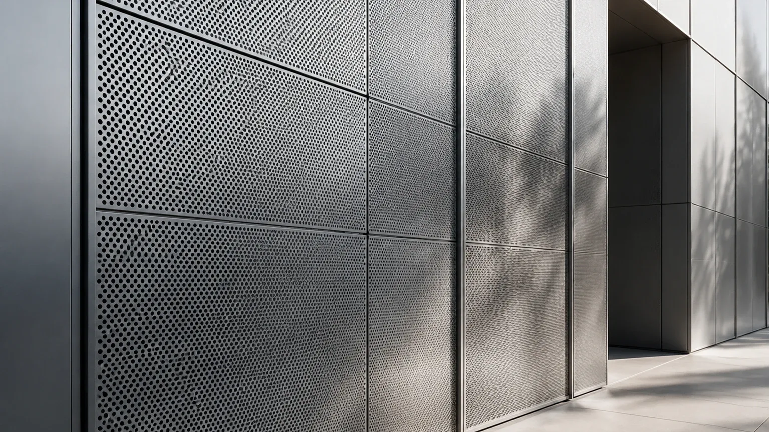
In modern industrial and architectural engineering, the integration of Building Information Modeling (BIM) has revolutionized how complex components are specified and fabricated. For engineers and project managers working with industrial filtration systems, acoustic barriers, or protective enclosures, utilizing a perforated metal wall revit family is more than a design choice; it is a critical step in ensuring that the transition from digital model to physical manufacturing is seamless.
When specifying Perforated & Expanded Metal for large-scale industrial projects, the accuracy of the Revit model directly impacts the procurement process, material waste, and the ultimate performance of the filtration or shielding system. This article explores the technical considerations required to align digital BIM workflows with the realities of stainless steel fabrication.
The Role of BIM in Specifying Perforated Metal Systems
Revit provides a platform where geometric data and material properties converge. For perforated metal walls, the software allows designers to visualize hole patterns, calculate weight, and assess the visual impact of different open areas. However, from a manufacturing perspective, a "perforated metal wall revit" model must be more than a visual representation; it must contain actionable data for the fabricator.
In many BIM workflows, perforated metal is often represented as a "cutout map" or a transparent texture to reduce the computational load on the software. While this is efficient for rendering, it lacks the precision needed for CNC punching or laser cutting. Engineers must ensure that the Revit family includes parameters for hole diameter, center-to-center spacing (pitch), and margin requirements. These data points are essential for Kaifil to translate a digital design into a high-precision stainless steel component that meets industrial tolerances.
Technical Parameters for Perforated & Expanded Metal Selection
Selecting the right material and pattern is the foundation of any successful filtration or structural project. Within the Revit environment, these selections should be guided by the physical limitations and performance characteristics of the metal.
Hole Patterns and Geometry
The geometry of the perforation affects both the structural integrity and the filtration efficiency of the panel. Common patterns include:
* Round Holes: The most common and versatile, offering a balance of strength and open area. They are typically arranged in a 60-degree staggered pattern for maximum efficiency.
* Square Holes: Often used for high open area requirements, though they may offer less structural rigidity than round holes under certain loads.
* Slotted Holes: Ideal for specialized filtration or drainage applications where directional flow is a factor.
Open Area Calculations
The "Open Area" percentage is a critical metric for any engineer. In Revit, this can be calculated using formulas based on the hole size and pitch. For industrial filtration, the open area determines the pressure drop across the wall and the flow rate of the medium. A higher open area reduces pressure resistance but may compromise the structural strength of the panel if the "bridges" (the metal between the holes) are too narrow.
Bridging the Gap Between Revit Modeling and Physical Fabrication
A common challenge in industrial procurement is the discrepancy between a Revit-generated schedule and the physical manufacturing constraints. When designing a perforated metal wall revit component, engineers should account for the following fabrication realities:
Margin and Border Requirements
In a digital model, it is easy to extend a perforation pattern to the very edge of a panel. In reality, manufacturing requires "margins"—unperforated areas along the edges. These margins provide space for welding, mounting holes, or structural framing. Failing to specify these in the Revit model can lead to panels that are difficult to install or prone to warping during the punching process.
Material Thickness and Gauge
The thickness of the stainless steel sheet must be compatible with the hole diameter. As a general rule of thumb in the industry, the hole diameter should not be smaller than the material thickness to avoid tool breakage and ensure clean cuts. If your Revit model specifies a 1mm hole in a 3mm stainless steel plate, it may require specialized laser cutting rather than standard punching, which significantly impacts the total cost and lead time.
Engineering Performance: Open Area and Structural Integrity
In industrial environments, perforated metal walls often serve dual purposes: acting as a filtration barrier and providing structural protection. The engineering of these panels requires a deep understanding of how the perforation process alters the base material's properties.
Stress Distribution
Perforating a metal sheet introduces stress concentrations around the holes. When a perforated metal wall revit model is subjected to structural analysis (such as FEA within or exported from Revit), it is vital to recognize that the effective yield strength of the perforated sheet is lower than that of a solid sheet. The direction of the staggered pattern also influences the panel's stiffness; panels are generally stiffer when loaded parallel to the stagger direction.
Acoustic and Thermal Properties
For walls used in engine rooms or industrial processing plants, acoustic attenuation is often a requirement. Perforated metal, when combined with sound-absorbing backing materials, acts as a resonant absorber. The Revit model should ideally include these acoustic properties as metadata to assist in the overall environmental analysis of the facility.
Material Selection and Durability in Industrial Environments
Kaifil specializes in stainless steel solutions because of the material's inherent resistance to corrosion and high temperatures. When defining the material in Revit, engineers must choose the appropriate grade based on the operating environment:
1. Grade 304 Stainless Steel: Suitable for most indoor industrial applications and general filtration. It offers excellent formability and weldability.
2. Grade 316 Stainless Steel: Essential for marine environments, chemical processing plants, or applications involving high chloride exposure. The addition of molybdenum provides superior pitting resistance.
3. Specialty Alloys: For extreme temperatures or highly corrosive media, specialized nickel alloys may be required.
Specifying the correct material grade within the Revit parameters ensures that the procurement team receives accurate quotes and that the final product will withstand the intended lifecycle, reducing the frequency of replacement cycles.
Customization and OEM Manufacturing for Complex Designs
One of the primary advantages of using a perforated metal wall revit workflow is the ability to create customized designs that are tailored to specific equipment or architectural requirements. Kaifil’s OEM capabilities allow for the production of non-standard hole shapes, variable perforation densities, and custom-formed panel geometries.
From BIM to CNC
Advanced manufacturers can often import CAD data directly from BIM software to program CNC machinery. This "File-to-Factory" workflow minimizes human error and ensures that the complex patterns designed in Revit are replicated with micron-level accuracy. Whether the project requires a simple protective screen or a complex multi-stage filtration wall, the digital data provides the blueprint for precision manufacturing.
Installation and Maintenance Considerations
The lifecycle of a perforated metal wall does not end with fabrication. Engineers must consider how these panels will be installed and maintained. Revit models should include details for fasteners, brackets, and joints.
* Ease of Cleaning: In food and beverage or pharmaceutical applications, the perforated wall must be accessible for cleaning. Smooth, burr-free perforations are essential to prevent the accumulation of contaminants.
* Replacement Cycles: By tracking the installation date and material specs within the BIM model, facility managers can predict replacement cycles based on the known wear rates of the specific stainless steel grade in their environment.
Conclusion: Optimizing Your Perforated Metal Procurement
Integrating a perforated metal wall revit family into your project is a powerful way to ensure technical accuracy and aesthetic consistency. However, the digital model is only as effective as its alignment with manufacturing capabilities. By focusing on critical parameters such as open area, margin requirements, material grade, and fabrication tolerances, engineers can leverage Perforated & Expanded Metal to its full potential.
When moving from the design phase to procurement, it is essential to partner with a manufacturer that understands the technical nuances of industrial filtration and metal fabrication. Providing a detailed Revit schedule or a high-quality CAD export allows for a more accurate quoting process and ensures that the final components meet the rigorous demands of industrial applications. For custom solutions that require precise engineering and durable performance, confirming these technical details early in the BIM process is the most effective path to project success.
