


Coalescing Filter Element
In industrial fluid processing, the separation of immiscible liquids or the removal of liquid aerosols from gas streams is a critical requirement for protecting downstream equipment and ensuring product purity. The coalescing filter element serves as the primary technical solution for these challenges. Unlike standard particulate filters that rely solely on mechanical straining to capture solid contaminants, a coalescing filter element utilizes specialized media to merge small droplets into larger ones, allowing them to be separated by gravity.
For engineers and procurement professionals, understanding the technical nuances of coalescing media, structural integrity, and fluid dynamics is essential for selecting a component that meets specific operational demands. As a manufacturer of custom filtration solutions, Kaifil emphasizes the importance of material compatibility and precision engineering in the development of high-performance coalescing systems.
Understanding the Mechanics of Coalescing Filtration
The operation of a coalescing filter element is governed by complex physical interactions between the fluid phase and the filter media. The process generally occurs in three distinct stages: capture, coalescence, and drainage.
1. Capture Mechanisms
As the contaminated fluid passes through the filter media—typically a graduated density matrix of borosilicate glass fibers or synthetic polymers—liquid droplets are captured through three primary mechanisms:
* Direct Interception: Occurs when a droplet follows a fluid streamline and comes into contact with a fiber because the distance between the streamline and the fiber is less than the droplet's radius.
* Inertial Impaction: Heavy droplets with higher momentum cannot follow the sharp turns of the fluid streamlines around fibers and instead collide directly with the media.
* Brownian Diffusion: Extremely small sub-micron droplets move randomly due to molecular collisions, increasing the probability that they will strike a fiber.
2. Coalescence
Once captured, the droplets adhere to the fibers. As more droplets are intercepted, they migrate along the fiber length and merge at the intersection points of the media. This process transforms microscopic aerosols into macroscopic droplets. The efficiency of this stage depends heavily on the surface tension of the liquids and the oleophobic or hydrophobic properties of the media coatings.
3. Drainage
The enlarged droplets eventually reach the outer surface of the filter element. Due to the increase in mass, gravity overcomes the viscous drag of the fluid stream, causing the droplets to fall into a collection sump. In gas-liquid applications, the gas typically flows from the inside of the element to the outside to facilitate this drainage process.
Material Engineering and Structural Design
The performance of a coalescing filter element is not solely dependent on the filtration media; the structural components are equally vital, especially in high-pressure industrial environments. For comprehensive information on custom builds, engineers can visit the Main Page to review technical specifications.
Support Cores and Cages
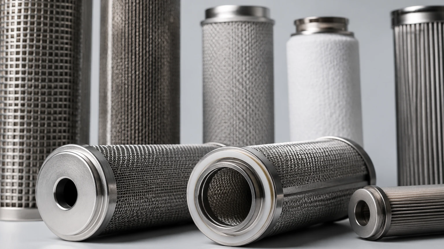
Industrial coalescing elements require robust internal and external support to withstand high differential pressures. These are typically constructed from stainless steel (304 or 316L). Perforated stainless steel cores provide the necessary rigidity to prevent media collapse during pressure surges, while expanded metal outer cages protect the delicate coalescing layers during installation and operation.
End Caps and Seal Integrity
End caps are usually manufactured from stainless steel or high-grade polymers, bonded to the media using specialized adhesives or thermal welding. The choice of sealing material (Buna-N, Viton, EPDM, or PTFE) is critical for chemical compatibility. A failure in the seal or the end cap bond results in "bypass," where contaminated fluid skips the filter media entirely, rendering the coalescing process ineffective.
Pre-filtration Layers
Many high-quality coalescing filter elements incorporate an integrated pre-filtration layer. This layer is designed to capture solid particulates before they reach the fine coalescing fibers. Without pre-filtration, solids can clog the interstitial spaces of the coalescing media, leading to a rapid increase in differential pressure and a shortened service life.
Critical Performance Metrics for Industrial Applications
When evaluating a coalescing filter element, engineers must look beyond simple micron ratings. Several key metrics determine the suitability of an element for a specific application.
Filtration Efficiency and Oil Carryover
In compressed air or gas applications, efficiency is often measured by "oil carryover," expressed in parts per million (ppm) or milligrams per cubic meter (mg/m³). A high-efficiency coalescing element can reduce oil content to as low as 0.01 ppm. In liquid-liquid separation, efficiency is measured by the percentage of the secondary phase removed from the primary phase.
Differential Pressure (Delta P)
The pressure drop across the filter element is a direct contributor to operational costs. A "dry" differential pressure refers to the resistance of a new, clean element, while "saturated" differential pressure accounts for the element when it is fully wetted with the liquid being coalesced. Engineers must ensure the system's pump or compressor capacity can handle the maximum saturated Delta P without compromising flow rates.
Surface Tension and Phobicity
The effectiveness of a coalescer is influenced by the interfacial tension between the two liquids (in liquid-liquid separation). If the interfacial tension is too low (e.g., below 20 dynes/cm), standard coalescing media may fail to merge the droplets effectively. In such cases, specialized surface treatments are required to modify the media's affinity for the dispersed phase.
Common Operational Risks and Failure Modes
Identifying potential risks before they lead to system failure is a core responsibility of maintenance and engineering teams. Coalescing filter elements are susceptible to several specific issues:
* Media Blinding: If the fluid contains high levels of solid contaminants and the element lacks adequate pre-filtration, the solids will block the media. This leads to premature pressure spikes.
* Surfactant Poisoning: Surfactants (surface-active agents) reduce the interfacial tension of the liquids. This can "disarm" the coalescer by allowing droplets to pass through the media without merging. This is a common issue in fuel filtration and chemical processing.
* Velocity Overload: Coalescing is a velocity-sensitive process. If the flow rate exceeds the design specifications, the high-velocity fluid can "re-entrain" the large droplets from the outer surface of the element, carrying them downstream.
* Chemical Degradation: Exposure to incompatible chemicals can weaken the binders used in the glass fiber media or degrade the seals, leading to structural failure of the element.
Technical Selection Criteria for Engineering Teams
To ensure the correct selection of a coalescing filter element, the following technical parameters must be confirmed during the procurement phase:
1. Fluid Properties: Identify the continuous phase (gas or liquid) and the dispersed phase (the liquid to be removed). Confirm the density, viscosity, and surface tension of both.
2. Operating Conditions: Specify the minimum, normal, and maximum operating pressures and temperatures. Temperature significantly affects viscosity and, consequently, coalescing efficiency.
3. Contaminant Loading: Estimate the concentration of the dispersed liquid phase (e.g., 500 ppm of water in oil) and the concentration of solid particulates.
4. Flow Rates: Provide accurate data on the volumetric flow rate. Sizing an element for the maximum possible flow is essential to prevent re-entrainment.
5. Target Cleanliness Levels: Define the required output purity (e.g., ISO Cleanliness Codes for hydraulic oil or residual oil content for compressed gas).
By providing these details to a manufacturer like Kaifil, engineers can receive customized filtration components tailored to their specific environmental constraints. For more information on available configurations, visit the Main Page.
Maintenance Protocols and Service Life Optimization
The longevity of a coalescing filter element is largely determined by the cleanliness of the incoming fluid and the stability of the operating environment. Monitoring differential pressure is the most reliable method for determining when an element requires replacement.
Monitoring and Replacement
Most industrial systems are equipped with differential pressure gauges. A common industry standard is to replace the coalescing element when the pressure drop reaches 0.5 to 0.7 bar (7 to 10 psi) above the initial saturated pressure drop, or annually, whichever comes first. Waiting until the pressure drop is excessive can lead to media rupture or the bypassing of contaminants through the relief valve.
Storage and Handling
Coalescing elements are precision instruments. They should be stored in their original packaging in a dry, temperature-controlled environment to prevent moisture absorption or physical damage to the media. During installation, technicians should handle the elements with clean gloves to avoid transferring skin oils to the media surface, which can create localized areas of different surface tension and affect performance.
System Flushing
When installing a new coalescing filter element into a system that has experienced a significant failure, it is advisable to flush the system to remove residual bulk contaminants. This prevents the new element from being immediately overwhelmed by the debris left behind by the previous failure.
In conclusion, the coalescing filter element is a sophisticated component that requires careful selection based on fluid dynamics and material science. By focusing on structural integrity and precise media engineering, industrial operations can achieve high levels of fluid purity, protecting both the environment and sensitive downstream machinery.
