


How Does a Coalescing Filter Work
In industrial environments, the presence of liquid aerosols, oil mists, and moisture in compressed air or gas streams can lead to catastrophic equipment failure, product contamination, and increased maintenance costs. While standard particulate filters are designed to capture solid debris, they are often ineffective against sub-micron liquid droplets. This is where the coalescing filter becomes an essential component of the filtration circuit. Understanding how does a coalescing filter work is critical for engineers and procurement teams tasked with maintaining high-purity environments in chemical processing, food and beverage production, and hydraulic systems.
Coalescing is a continuous process where small droplets of liquid are merged into larger drops as they pass through a specialized filter medium. Unlike a particulate filter, which eventually clogs and must be cleaned or replaced, a coalescing filter is designed to facilitate the migration and drainage of liquids, allowing for long-term operation in demanding industrial applications.
The Fundamental Principles of Coalescence
To answer the question of how does a coalescing filter work, one must first look at the physics of fluid dynamics at the microscopic level. Coalescence is the opposite of atomization. While an atomizer breaks a liquid into a fine mist, a coalescer takes that mist and forces it back into a bulk liquid state.
In a typical industrial setup, the filter media is composed of a dense mat of borosilicate micro-fibers or specialized stainless steel wire mesh layers. As the contaminated gas or liquid stream enters the filter element, it is forced through these fibers. The process relies on three distinct physical mechanisms: direct impaction, interception, and diffusion (Brownian motion). By combining these three actions, the filter can capture aerosols as small as 0.01 microns with efficiencies exceeding 99.9%.
The Three Stages of Aerosol Removal
The efficiency of a coalescing filter is not dependent on a single action but rather a sequence of physical interactions between the contaminant and the filter fibers. These stages are categorized based on the size of the droplets being removed.
1. Direct Impaction
Direct impaction occurs with larger liquid droplets, typically those greater than 1 micron in diameter. These droplets have enough mass and momentum that they cannot follow the streamlines of the gas as it curves around the filter fibers. Instead, the droplets continue in a straight path, colliding directly with the fibers and adhering to them due to surface tension.
2. Interception
Interception targets medium-sized droplets, usually between 0.1 and 1 micron. These droplets are light enough to follow the gas streamlines, but as the gas passes close to a fiber, the distance between the droplet's center and the fiber becomes less than the droplet's radius. The droplet touches the fiber and becomes trapped. This mechanism requires precise engineering of the fiber density to ensure maximum contact without creating an excessive pressure drop.
3. Diffusion (Brownian Motion)
For the smallest aerosols, typically those below 0.1 microns, the primary mechanism is diffusion. These tiny particles do not follow the gas streamlines; instead, they move in a random, zig-zag pattern caused by collisions with gas molecules (Brownian motion). This erratic movement increases the probability that the particles will eventually bump into a filter fiber and be captured. This is why coalescing filters are often more efficient at removing extremely small particles than medium-sized ones.
The Transition from Aerosol to Bulk Liquid
Once the droplets are captured by the fibers, the second phase of the process begins. As more droplets collect on the fibers, they begin to run together, or "coalesce," forming larger drops. These larger drops are pushed through the depth of the filter media by the force of the gas flow.
In most industrial coalescing filters, the flow direction is from the inside of the element to the outside. This "inside-out" flow ensures that as the droplets grow in size, they move toward the outer surface of the filter. Once they reach the outer layer—often a porous drainage shroud made of specialized foam or stainless steel mesh—gravity takes over. The heavy drops fall to the bottom of the filter housing, where they collect in a sump and are eventually removed via a manual or automatic drain. This continuous drainage allows the filter to handle high liquid loads without becoming saturated.
Structural Components and Material Selection
The performance of a coalescing filter is heavily dependent on its construction. For industrial applications involving corrosive chemicals or high temperatures, the choice of materials is paramount. Manufacturers like Kaifil specialize in providing the internal support structures and precision metal components that ensure the filter media remains stable under high differential pressures.
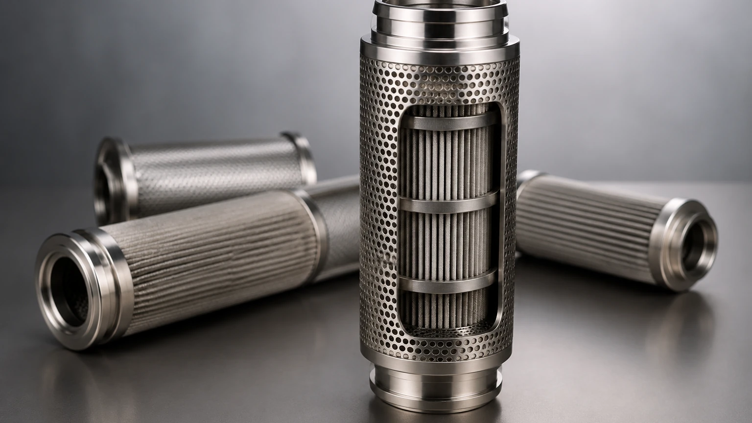
* The Inner Support Core: Usually made of perforated stainless steel, this provides the structural integrity to prevent the filter media from collapsing under the pressure of the incoming gas.
* The Coalescing Media: This is the heart of the filter, often consisting of multiple layers of varying fiber diameters to maximize the capture of different particle sizes.
* The Outer Support and Drainage Layer: A secondary stainless steel mesh or foam layer that protects the media and facilitates the downward flow of the coalesced liquid.
* End Caps: Precision-machined components that ensure a leak-proof seal within the filter housing.
For more information on the engineering of these components, you can visit the Main Page to review product options and application support.
Coalescing vs. Particulate Filtration: Key Differences
It is a common mistake in procurement to treat coalescing filters and particulate filters as interchangeable. While they may look similar, their engineering objectives are different. A particulate filter is designed to stop solids on the surface or within the depth of the media. If a particulate filter is used to remove oil aerosols, it will quickly become "blinded" or saturated, leading to a massive pressure drop and potential media rupture.
Conversely, a coalescing filter is designed to be "wet." Its efficiency actually improves slightly as the fibers become coated with liquid, as this facilitates the merging of new droplets. However, coalescing filters are sensitive to solid contaminants. If the gas stream contains high levels of dust or scale, a particulate pre-filter should be installed upstream to protect the delicate micro-fibers of the coalescer. This two-stage approach extends the service life of the more expensive coalescing element and ensures consistent air quality.
Factors Affecting Performance and Efficiency
When evaluating how does a coalescing filter work in a specific application, several variables must be considered to ensure the system meets the required ISO 8573-1 air quality standards.
1. Flow Velocity: Coalescence is highly sensitive to velocity. If the gas moves too quickly, it can "re-entrain" the liquid drops, stripping them off the outer surface of the filter and carrying them downstream. Proper sizing is essential to maintain a laminar flow profile.
2. Temperature: Higher temperatures reduce the surface tension and viscosity of oils and liquids. This can make it harder for droplets to adhere to the fibers and coalesce, potentially reducing filtration efficiency.
3. Surface Tension: The chemical properties of the liquid being removed affect how easily it wets the filter fibers. Synthetic lubricants used in modern compressors often require specifically treated media to ensure effective coalescence.
4. Pressure Drop (Differential Pressure): As the filter captures liquid, there will be a natural resistance to flow. A high-quality coalescing filter should maintain a low initial pressure drop (usually 1-2 psi) and should be replaced once the differential pressure reaches a predetermined limit (typically 8-10 psi), as the energy cost of pushing air through a saturated filter outweighs the cost of a replacement element.
Applications in Industrial Sectors
Coalescing filters are used across a broad spectrum of industries where dry, oil-free gas is a requirement:
* Compressed Air Systems: Protecting pneumatic tools, control valves, and air motors from oil and water contamination.
* Natural Gas Processing: Removing liquid hydrocarbons and water from gas streams to prevent damage to turbines and compressors.
* Food and Beverage: Ensuring that air used for packaging or ingredient mixing is free from oil mists that could affect taste or safety.
* Pharmaceuticals: Maintaining sterile, oil-free environments for chemical synthesis and pill coating.
* Petrochemical: Separating water from fuel or oil in refinery processes using liquid-liquid coalescers.
Maintenance and Total Cost of Ownership
Understanding the mechanics of a coalescing filter also involves understanding its maintenance lifecycle. Unlike a simple mesh screen, a coalescing element has a finite life dictated by the accumulation of solid particulates that the pre-filter missed.
Engineers should monitor the differential pressure regularly. A sudden drop in pressure might indicate a "burst" or channeled media, meaning the filter is no longer providing protection. A steady, slow rise is normal. By selecting high-quality stainless steel support components and validated filter media, facilities can reduce the frequency of change-outs and ensure that the downstream equipment remains protected from liquid carryover.
When sourcing these components, it is vital to work with manufacturers who understand the nuances of filtration accuracy and material compatibility. Providing the right filtration solution involves more than just selling a part; it requires an engineering-first approach to material selection and structural design to ensure the filter performs reliably in demanding industrial environments.
