


Oil Filter Oil Flow Direction
In industrial filtration systems, the performance and longevity of machinery depend heavily on the precise management of fluid dynamics. One of the most critical, yet sometimes overlooked, aspects of hydraulic and lubrication system design is the oil filter oil flow direction. Understanding the path that fluid takes through a filter element is not merely a matter of installation convenience; it is a fundamental engineering requirement that dictates the structural integrity of the filter, the efficiency of contaminant capture, and the safety of the downstream components.
For engineers and procurement professionals sourcing stainless steel filtration solutions, identifying the correct flow orientation is essential for preventing catastrophic system failures. Whether dealing with high-pressure hydraulic circuits or high-temperature chemical processing lines, the direction of flow determines how the filter media is supported and how the internal valves operate.
The Fundamentals of Industrial Oil Flow Direction
Industrial oil filters are typically designed for one of two primary flow patterns: outside-in (standard) or inside-out. The choice between these configurations is rarely arbitrary and is usually dictated by the housing design and the specific requirements of the application.
Outside-In Flow
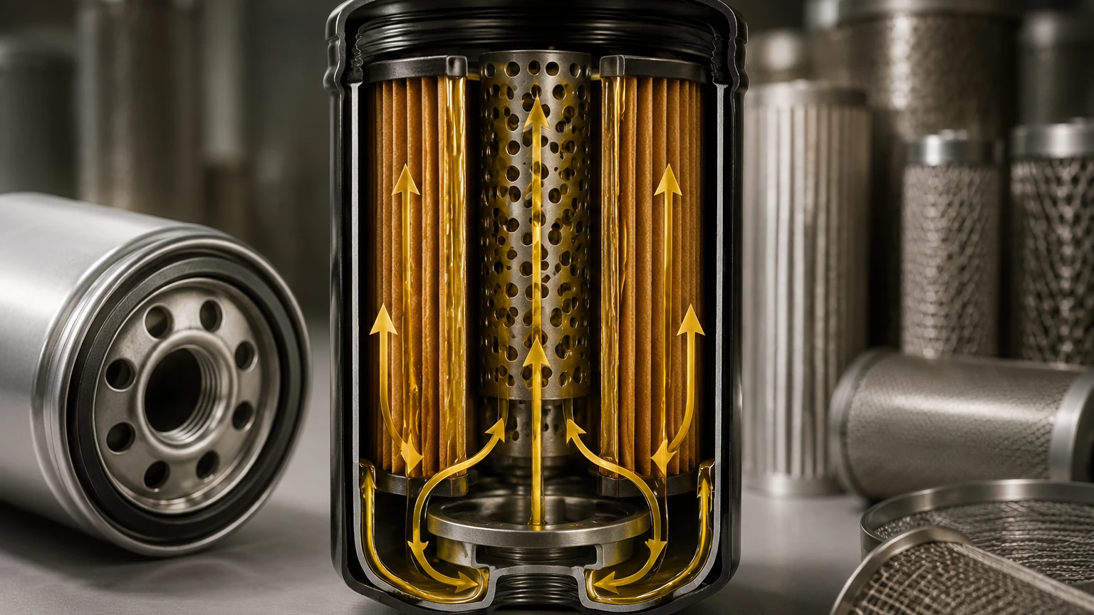
The majority of industrial spin-on filters and cartridge-style elements utilize an outside-in flow pattern. In this configuration, the contaminated oil enters the filter housing, surrounds the exterior of the filter element, and passes through the media toward the hollow center tube. The clean oil then exits through the center of the mounting head.
This design is preferred in many B2B applications because it maximizes the effective filtration surface area. By utilizing the outer circumference of the pleated media as the entry point, the filter can handle higher dirt-holding capacities before the pressure drop (ΔP) reaches critical levels. Furthermore, the structural design of these filters often includes a perforated metal inner core that provides necessary support against the inward pressure of the fluid, preventing the media from collapsing.
Inside-Out Flow
While less common in standard hydraulic systems, inside-out flow is frequently used in specialized applications, such as coalescing filters or certain high-viscosity lubrication systems. In this setup, the oil enters the center of the element and is forced outward through the media. This orientation is sometimes chosen to keep captured contaminants trapped inside the element, making it easier to remove the debris during a filter change without cross-contaminating the clean side of the housing.
Engineering Impact of Flow Direction on Filter Performance
The oil filter oil flow direction directly influences the mechanical stress placed on the filter media. In a professional industrial setting, filters are subjected to varying flow rates, pressure spikes, and changes in fluid viscosity. If the flow direction is reversed or if a filter is installed in a system not designed for its specific flow path, several technical issues arise.
Structural Integrity and Support
Filter elements are engineered to withstand pressure from a specific direction. For an outside-in filter, the internal center tube (often made of 304 or 316L stainless steel) acts as a backbone. As the differential pressure increases due to contaminant loading, the media is pushed against this core. If the flow were reversed (inside-out), the media would be pushed away from the core. Without an external support cage or specialized pleat bonding, the media would likely rupture or "balloon," leading to a total loss of filtration and potential downstream contamination.
Pressure Drop (ΔP) Characteristics
Flow direction affects the fluid velocity as it passes through the media. In an outside-in configuration, the fluid moves from a larger surface area to a smaller one. This transition must be carefully managed to avoid excessive turbulence. Engineers must calculate the clean pressure drop based on the intended flow direction to ensure the system pump is not overworked and that the fluid remains within the laminar flow regime as much as possible.
Identifying Oil Filter Oil Flow Direction in the Field
For maintenance teams and system integrators, identifying the correct oil filter oil flow direction is a prerequisite for any installation. Most industrial filter housings and elements include specific indicators to guide this process.
1. Housing Markings: High-quality industrial filter heads usually feature cast-in arrows or stamped labels indicating "IN" and "OUT" ports. These markings are the primary reference for plumbing the hydraulic or lubrication lines.
2. Element Construction: By examining the physical build of a stainless steel cartridge, one can often deduce the intended flow. A heavy-duty perforated core on the inside suggests outside-in flow, whereas an external mesh wrap or cage without an internal core might suggest the opposite (though many high-performance filters utilize both for maximum durability).
3. Valve Orientation: If the filter includes an integrated bypass valve or an anti-drainback valve, these components are unidirectional. A bypass valve is designed to open when the pressure on the inlet side exceeds a specific threshold relative to the outlet side. If the flow is reversed, the bypass valve will remain permanently closed or fail to function, leading to media rupture under high differential pressure.
Risks Associated with Reversed Flow Orientation
Installing a filter contrary to its designed oil filter oil flow direction introduces significant risks to industrial equipment. These risks extend beyond the filter itself and can impact the entire production line.
* Media Migration: When fluid flows in the wrong direction, it can strip fibers or particles from the "clean" side of the filter media and carry them directly into sensitive components like servo valves, bearings, or high-pressure pumps.
* Bypass Failure: As mentioned, bypass valves are directional. In a reversed flow scenario, if the filter becomes clogged, the system may have no way to bypass the element. This results in a massive pressure spike that can burst seals or damage the pump.
* Pleat Collapse: Industrial filters often use pleated wire mesh to increase surface area. These pleats are designed to be supported in a specific direction. Reversed flow can cause the pleats to bunch together or flatten, drastically reducing the effective filtration area and causing an immediate, sharp increase in pressure drop.
Customization and OEM Solutions for Specific Flow Requirements
In many complex B2B environments, standard off-the-shelf filters do not meet the unique flow or chemical compatibility requirements of the process. This is where custom stainless steel filtration solutions become necessary. Manufacturers like Kaifil specialize in engineering filter elements that are tailored to specific flow directions and environmental conditions.
When designing a custom filter, engineers must confirm the following parameters related to flow:
* Operating Temperature: High temperatures can affect the structural strength of the filter media and its support structures, making the correct flow orientation even more critical for maintaining shape.
* Fluid Chemistry: In chemical processing, the direction of flow may impact how corrosive fluids interact with the welded seams of a stainless steel filter.
* Mechanical Vibration: Systems with high vibration require robust support cages on both the interior and exterior of the media to ensure that the flow direction does not cause fatigue-induced cracking of the wire mesh.
By working with a specialized manufacturer, companies can ensure that their Main Page and product selections are perfectly aligned with the technical realities of their machinery. Custom end caps, specialized threading, and reinforced cores can all be adjusted to accommodate non-standard oil filter oil flow direction requirements.
Maintenance and Installation Best Practices
To ensure optimal performance, B2B procurement and maintenance teams should implement strict protocols regarding filter orientation.
Verification During Replacement
Every time a filter element is replaced, the technician should verify that the new element matches the flow specifications of the housing. This is particularly important when switching between different suppliers or OEM alternatives. Even if the dimensions are identical, the internal flow path or valve settings may differ.
Monitoring Differential Pressure
Installing differential pressure gauges upstream and downstream of the filter is the best way to monitor the health of the system. A sudden drop in differential pressure might indicate that the media has ruptured due to incorrect flow orientation, while a faster-than-normal increase might suggest that a reversed-flow installation is causing pleat blinding.
Cleaning Reusable Stainless Steel Filters
For industries using cleanable stainless steel wire mesh filters, the oil filter oil flow direction is also relevant during the cleaning process. Backwashing—forcing cleaning fluid in the opposite direction of the operational flow—is a common technique to dislodge trapped contaminants. However, the filter must be designed to withstand this reverse pressure during the cleaning cycle without damaging the mesh.
Conclusion
The oil filter oil flow direction is a cornerstone of industrial filtration engineering. It dictates how a filter is built, how it performs under pressure, and how it protects expensive machinery. By prioritizing the correct identification and implementation of flow paths, engineers can reduce downtime, lower maintenance costs, and extend the service life of their equipment. For those seeking high-performance, customized filtration components, consulting with experts who understand these technical nuances is the most effective way to ensure system reliability. Always confirm the flow requirements of your specific application before finalizing a purchase or installation plan.
