


Woven Wire Mesh Cad
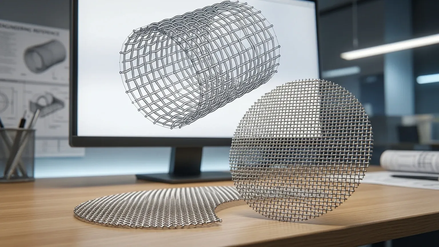
In the realm of industrial filtration and precision engineering, the transition from conceptual design to a functional physical component requires meticulous accuracy. For engineers designing filtration systems, acoustic baffles, or structural screens, incorporating woven wire mesh cad data into a larger assembly is a critical step. Woven wire mesh is a complex material characterized by its geometric regularity and specific performance metrics, such as open area and micron rating.
As a professional manufacturer, Kaifil understands that providing accurate technical data is essential for the success of complex engineering projects. This guide explores the technical considerations, modeling strategies, and procurement workflows associated with woven wire mesh CAD to help technical teams optimize their design-to-manufacture pipeline.
The Role of CAD in Woven Wire Mesh Specification
Computer-Aided Design (CAD) serves as the bridge between theoretical filtration requirements and the final manufactured product. When an engineer integrates a woven wire mesh cad model into their project, they are typically looking to solve three primary challenges: spatial fit, fluid dynamics simulation, and structural integrity.
Spatial Fit and Assembly Integration
In applications such as hydraulic filters or pharmaceutical strainers, the mesh must fit perfectly within a housing or over a support core. CAD allows designers to account for the thickness of the mesh—which is often twice the wire diameter in plain weaves—and ensure that tolerances are maintained after the mesh is rolled, welded, or pleated.
Performance Simulation
Advanced engineering often requires Computational Fluid Dynamics (CFD) to predict pressure drops across a filter element. Accurate CAD geometry of the Plain, twill and dutch woven wire mesh in SS304/316L — rolls, cut mesh and framed panels. Send mesh count or micron target for a technical quote. allows for the creation of a mesh grid that simulates how fluids or gases interact with the wire surfaces. This is vital for ensuring that the chosen mesh count does not restrict flow beyond acceptable limits.
Translating Physical Mesh Characteristics to Digital Models
To create or use a woven wire mesh cad file effectively, one must understand the fundamental parameters that define the material. Woven wire mesh is not a monolithic block; it is a precision-engineered textile of metal wires. The following parameters must be accurately represented in any digital model:
1. Mesh Count: The number of openings per linear inch. This determines the density of the grid in the CAD model.
2. Wire Diameter: The thickness of the individual wires before weaving. This affects both the strength of the mesh and the resulting open area.
3. Aperture (Opening Size): The clear distance between adjacent wires. In CAD, this is the most critical dimension for filtration simulations.
4. Weave Type: Whether the mesh is plain, twill, or dutch woven. Each weave type has a unique 3D profile that changes how the mesh occupies space and handles pressure.
Modeling Different Weave Types
* Plain Weave: The simplest form where each shute wire passes over and under one warp wire. In CAD, this is modeled as a repeating sine-wave pattern in two axes.
* Twill Weave: Used for heavier meshes or finer filtration, where wires pass over and under two wires. This creates a diagonal pattern that requires more complex 3D paths in CAD software.
* Dutch Weave: This involves different wire diameters for warp and shute wires, resulting in a much tighter, "zero-aperture" appearance. Modeling Dutch weave in CAD is particularly challenging due to the overlapping geometry and is often represented by a simplified porous media block in large-scale simulations.
Engineering Considerations for Material Selection
When working with woven wire mesh cad, the choice of material is as important as the geometry. At Kaifil, we primarily work with stainless steel alloys due to their durability and resistance to corrosion and high temperatures. The choice between SS304 and SS316L must be documented within the CAD metadata to ensure the final Bill of Materials (BOM) reflects the environmental requirements of the application.
* SS304: Suitable for general industrial use, offering excellent strength and basic corrosion resistance.
* SS316L: Preferred for marine, chemical processing, and pharmaceutical applications where resistance to chlorides and acids is paramount.
In a CAD environment, specifying the material also allows for accurate weight calculations. For large-scale filtration units, the weight of the Woven Wire Mesh can impact the design of the support structures and the overall cost of shipping and installation.
Challenges and Risks in Woven Wire Mesh CAD Modeling
While CAD is an invaluable tool, it presents specific challenges when dealing with woven materials. Engineers must balance the need for detail with the practicalities of software performance.
The File Size Paradox
One of the most common issues with woven wire mesh cad is the sheer number of geometric entities. A high-mesh-count screen can contain thousands of individual wire segments. If every wire is modeled as a 3D solid, the file size can become unmanageable, leading to slow render times and system crashes.
Solution: For large assemblies, engineers often use a "simplified representation." This involves using a flat sheet with a mapped texture or a transparent property to represent the mesh, only switching to a detailed 3D model for localized stress analysis or CFD in a specific area.
Manufacturing Discrepancies
CAD models are mathematically perfect, but physical weaving involves tolerances. The "crimp" of the wire—the slight deformation where wires cross—can vary slightly depending on the loom tension. When designing parts that require a press-fit or tight seal, it is essential to consult with the manufacturer to confirm the actual thickness of the finished Woven Wire Mesh rather than relying solely on the theoretical CAD thickness.
Optimizing the Procurement Process with CAD Data
Using woven wire mesh cad data effectively can significantly streamline the procurement process. When submitting a Request for Quote (RFQ) to a manufacturer like Kaifil, providing a CAD file or a detailed technical drawing derived from CAD ensures that there is no ambiguity regarding the requirements.
Confirmation Steps for Engineers
Before finalizing a design and moving to the purchasing phase, engineers should confirm the following with their filtration partner:
1. Effective Filtration Area (EFA): Does the CAD model accurately reflect the open area available after the mesh is welded into its frame?
2. Structural Support: For high-pressure applications, does the CAD model include the necessary support mesh or perforated metal backing?
3. Edge Treatment: How will the edges of the mesh be handled? CAD models should specify if the mesh will be hemmed, framed, or left with raw edges to prevent fraying during installation.
By integrating these considerations into the early stages of the design process, technical teams can avoid costly revisions and ensure that the final Woven Wire Mesh component performs exactly as intended in its industrial environment.
Conclusion: Precision from Design to Delivery
In modern industrial manufacturing, woven wire mesh cad is more than just a visual aid; it is a fundamental component of the engineering workflow. Whether you are designing a custom filter cartridge for a chemical plant or a precision screen for food processing, the accuracy of your digital model directly impacts the quality of the physical product.
At Kaifil, we combine manufacturing expertise with technical support to help our clients navigate the complexities of mesh selection and integration. By focusing on factual engineering data—from mesh counts and micron ratings to material properties and weave geometries—we ensure that our Woven Wire Mesh solutions meet the most demanding industrial standards. For engineers and purchasing teams, leveraging accurate CAD data is the first step toward achieving efficient, durable, and cost-effective filtration performance.
